UPDATED JULY 2023
I have performed, literally, thousands of modifications in my audio career. The first was around 1979*, when I changed an amplifier, with the help of a friend, from pentode into triode. Then in 1981, when an (then new) audiophile friend encouraged me to change the coupling capacitors in that same power amplifier (the Dynaco Mk. VI). The improvements I heard, at such a modest cost, permanently changed my audio life.
I feel that modifications, more than anything else besides speaker/room optimization and system matching, are the key to creating a "great" sound system, instead of accepting just good or even impressive. In fact, I've never heard a truly great system that was NOT modified in some manner.
Even for those audiophiles who have more modest goals, such as simple satisfaction and/or the "best audio bang for the buck", I know of no other method to improve your existing system to as great a degree, for as little money. In short, modifications are the best and most economical audio investment you will ever experience.
This file will focus on modifications; simple and easy, and difficult and complex. I will give the reader the fullest extent possible of the experiences I, and others, have had over the last 40 years and more.
Caveat- I only recommend modifying equipment when:
1. It is in full, proper working condition.
2. You are already satisfied with its performance.
Modifications are not "repairs", and modifications will not turn an unsatisfactory component (to your ear) into a component you enjoy and love. Modifications enhance what you have. I've never experienced a modification which can transform what the listener does not like. That overly optimistic goal is most likely impossible with only a modification.
*Actually, in 1974, I added an outboard capacitor bank to a CM Labs 911 power amplifier, with the help of a more technically skilled friend. Maybe that was "my first modification". That mod was inaudible both to me, and my equally disappointed friend, so my career in modifications didn't exactly begin on a successful note.
TopElectronic components, especially tube audio equipment, operate at lethal voltages. The information provided on the following pages is intended for educational purposes only and are written for electronics hobbyists who understand the safety precautions that must be observed when working with high voltage circuits. Do not attempt to modify any electronic components unless you are competent to use this information safely. You, alone, are responsible for taking every available safety precaution. Arthur Salvatore, and High-End Audio, specifically disclaim any liability whatsoever for any injury suffered, directly or indirectly, as a consequence of the use of the information provided on this website, including, without limitation, the following WebPages(s).
The information provided on this website reflects the perspective of the author, Arthur Salvatore, based on personal listening preferences. Music appreciation is subjective, and your preferences may differ from those of the author. The author offers no assurance whatsoever that the information (including the specific modifications detailed herein) will be satisfactory to you. Moreover, the author makes no representation or warranty whatsoever that the modifications detailed on the following WebPages(s) will operate properly in your electronic components. Finally, there is a high probability that modifying an electronic component will void the manufacturer's warranty.
You are only entitled to read and/or use the information provided on the following WebPages(s) if you first agree to the waivers of liability and the disclaimers of any representations and warranties detailed in the forgoing sections titled "Health and Safety Warning" and "Compatibility and Applicability Warning." Any reading or use of the following information shall be deemed de facto evidence of your acceptance of these terms.
TopI will describe the extensive modifications that were made on the Jadis JP-80 preamplifier, which I have used as a reference since 1989. These modifications, in part or in whole, can also be performed on most other tube preamplifiers.
Every tube preamplifier has coupling capacitors (the caps actually in the signal path to block DC), and these caps must be at least excellent in quality to optimize that preamp's inherent sonic potential. Improving these capacitors is the most elementary and important modification that can be made. It is also, obviously, the most easily heard and appreciated.
The second part of the "basic" modification is the "shunting" (or "bypassing") of the decoupling capacitors. These caps are the local power supply (not signal path) capacitors that both filter and store the DC energy which the "plate" of the tube requires to actually amplify the signal.
They can be either electrolytic (+ or -) or "film" in type. Film are preferable because they're "faster", and are now commonly used with most preamplifier designs, even the less expensive models. Unfortunately, most decoupling caps don't have an extra, tiny (.1uf or .01uf) cap to provide instantaneous energy, so adding these tiny caps is also a must. This part of the modification will be more subtle than the above, but still quite noticeable and vital for total optimization.
The details:
The JP-80 is a straightforward preamplifier, with 6 tubes, all of them 12AX7 types; Three in the phono stage and three in the linestage. The circuit is very similar to the Marantz 7C. The newer MC version of the JP-80 has more tubes in its head-amp circuit, which we will ignore.
The phono stage has two capacitors in the signal path. The first cap is between the first and second tubes. These are the tubes that provide the RIAA equalization and amplification. The second cap is the phono stage's output coupling cap. The third tube, the cathode follower, which does not actually amplify the signal, sends the transformed signal through this cap to the selector control.
The first coupling cap is .47uf at 1000 Volts and was made in Europe. While it was "full-bodied", nothing else about it was exceptional. In particular, it was slow and veiled. There's approximately 400 volts on the plate of the first tube, so I would look for a 600 volt cap to replace it, 1000 volts is probably overkill. The .47uf size should be adhered to, unless you will accept a slight roll-off in the deepest bass (or are willing to make a minor change in the R/C circuit).
The big decision is what to replace the .47 cap with?! There are a number of choices, which I will get into more detail later. Here's a short list for now:
1. REL caps, polypropylene or polystyrene film and foil, or even Teflon
2. Infini Signature caps, or their more recent advanced models the "DynamiCaps"
3. Hovland Music caps
4. Auricaps
5. MIT caps, polypropylene and polystyrene film and foil, metallized (and the Teflon "Exotica", which I haven't been able to find anywhere on the web)
6. PAS caps (if they are still made)
7. Others I've temporarily forgotten
A .01uf 600V cap, of the same type, should be used in parallel with the .47uf, which will speed it up just a touch. Some people don't like the results, but the listener should make up his/her own mind on this. I prefer using the .01uf myself.
The output (coupling) capacitor is very different from the (interstage) coupling capacitor. Jadis did something here I've never seen before or since. They put eleven (11) capacitors in parallel! This was, apparently, to avoid using one large capacitor, which they felt would have too much of a high-frequency roll-off (or inductance). The total capacitance of all 11 caps combined is around 6.5 uf. Unfortunately, the use of 11 caps causes its own problems; a lack of cohesion and focus and mediocre bass, so they must be replaced.
The best solution to this problem is to find one capacitor as close as possible to 6.5 uf (and preferably larger) and add a .01 uf cap as a shunt ("tweeter" cap). This is what I did myself. I used a large MIT metallized cap (20 uf if I remember correctly) and shunted it with another MIT cap, a .01uf 630 volt polystyrene. (I don't use these caps today, but that will be discussed in the "Extreme Modification" section.) Fortunately, the output cap only has to handle around 200 volts*, so 300 or 400 volt capacitors are fine.
*There are inital voltage surges greater than the final static voltage, so owners of other preamplifiers should measure the surge voltages before choosing the voltage value of the capacitor they are going to use.
The line-stage of the JP-80 has the exact same interstage cap, but the output "cap" is actually 5 caps in parallel this time instead of 11, and the total capacitance is around 5.2 uf. The modification for the line stage is almost exactly the same, except the replacement output caps can be slightly smaller, but the use of a .01uf shunt cap is still advised (400 volt caps in this position are fine). There is one other difference though...
The JP-80 has an INPUT cap (1 uf) at the beginning of the line-stage circuit. This means that the signal from all the line sources, including the signal from the phono stage, must pass through this cap. The owner/user has a choice here, either replace this 1 uf cap with something better (and adding a .01 uf shunt), or removing the capacitor altogether. At this time, I advise simply replacing the input cap with a better cap. (I actually prefer removing the cap, but this will be done at a later time, specifically during the "Advanced" modification).
This finishes the coupling capacitor part of the modification. I highly recommend changing only one capacitor at a time (both channels at once though). By changing the caps in stages, you will hear each improvement separately, and, if there is a problem, there will be no guess work as to the exact source of the problem. In most cases, the change of coupling caps will be the largest improvement of any modification advised in this file. In some instances, where the stock coupling caps are really bad, the preamplifier will even sound transformed, with much greater transparency, immediacy, purity and dynamic qualities. More extended highs and bass are also common. This is why I recommend modifying something you already like and enjoy before making an expensive move "up", because it may not be necessary.
The JP-80, and other tube preamplifiers, will have electrolytic capacitors storing DC energy near the tubes. They will be connected to the plates of the tubes, though not directly. There will be a large resistor between the capacitor and the plate of the tube. These caps will not be replaced this time. Instead, there will be "shunt" capacitors soldered in parallel with (usually on top of) them. Depending on the amount of space there is, a .1 uf can be used, or, with plenty of space, a 1 uf cap, with a smaller .01 uf shunt cap, can be used together. The shunt caps must have a voltage rating at least as high as the caps that are already there. They must be soldered strictly in parallel with the existing electrolytic, meaning on their side of the resistor (and not on the tube's side).
More modern preamplifiers may already have shunts on their electrolytics, or have even eliminated the electrolytics and already used only film capacitors. In these cases, the user must decide whether these more advanced de-coupling caps can still be improved with even better brands. If so, the advice above still holds. Also, the larger the film cap shunt, assuming a .01 uf is used with it, the better, everything being equal, but the new, larger cap must be positioned tightly and safely, and never loosely.
Once again, I recommend doing only one stage, though on both channels, at a time, and then listening. In the case of the JP-80, this means 6 separate stages, since it has a separate de-coupling capacitor for each (double) plate on the 6 tubes.
The sonics effects are less noticeable than the changing of the coupling caps, but are still important. These shunt caps will allow more space, air, decays and harmonics to be heard. The soundstage should sound larger, and more focused. There could also be a slightly greater sense of speed and purity, though not as dramatic as a signal path cap change.
This finishes the "Basic" modification. This modification should be performed on all older preamplifiers, and many modern preamps that don't use the finest available capacitors in their signal paths, or are budget models which don't include shunts on their local de-coupling caps. Also, some designers still don't believe that capacitors make a sonic difference and that shunts are a waste of money. This means that even their expensive models can be easily improved at a modest cost.
For most readers, this basic modification will be both the beginning and the end of the line for them, since it focuses on the fundamental execution of the existing design, but does not change that design. The next level of modification begins to change the circuit itself, though subtly. The differences will not be as dramatic, but will still be noticeable and well appreciated.
Remove Line Stage Input Capacitor
Change the RIAA Equalization Curve (to Dr. Stanley Lipschitz's- the most accurate I'm aware of at this time)*
Remove the Tape Relay from the Circuit
Remove the resistor and the RFI capacitors at the phono input
*The signal goes from the output (plate) of the second RIAA tube to the cathode of the first RIAA tube:
1. Soldered to the second RIAA tube plate: a 1.21m ohm resistor and a 2,640 pf cap in parallel, this signal goes (soldered) to a;
2. 100k ohm resistor and 750pf cap, also in parallel;
3. the output of this goes (is soldered) to the cathode of the first RIAA tube.
Remove the Entire Line Stage from the Signal Path
Replace all the relevant Electrolytic capacitors in the Power Supply with Film Types and Bypasses
Replace all the De-coupling Electrolytics in the Preamplifier with Film Types and Bypasses
Remove (bypass) the Mute Switch from the Circuit
Remove (bypass) the Cathode Follower Tube at the output of the Phono Stage
Remove the Volume Control** (and possibly even the Selector Switch) from the Direct Signal Path
**Use a 1M OHM resistor to ground as the load.
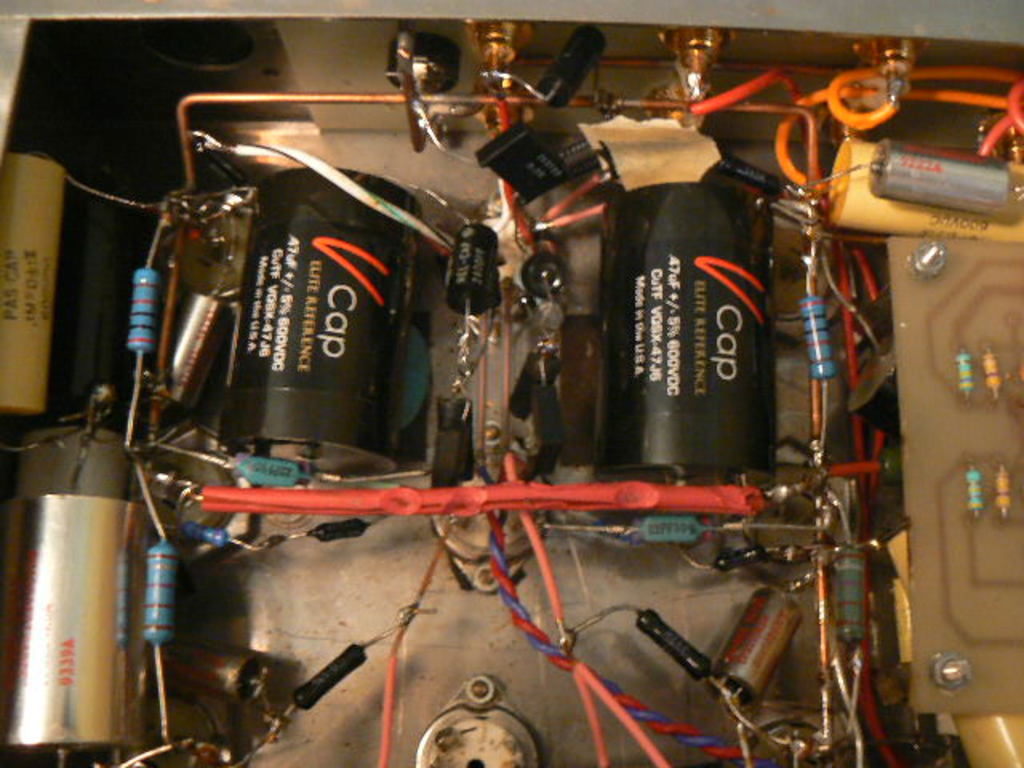
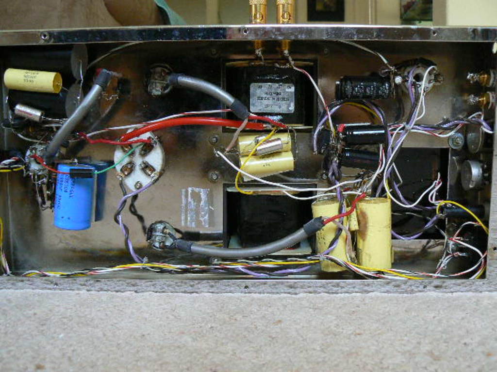
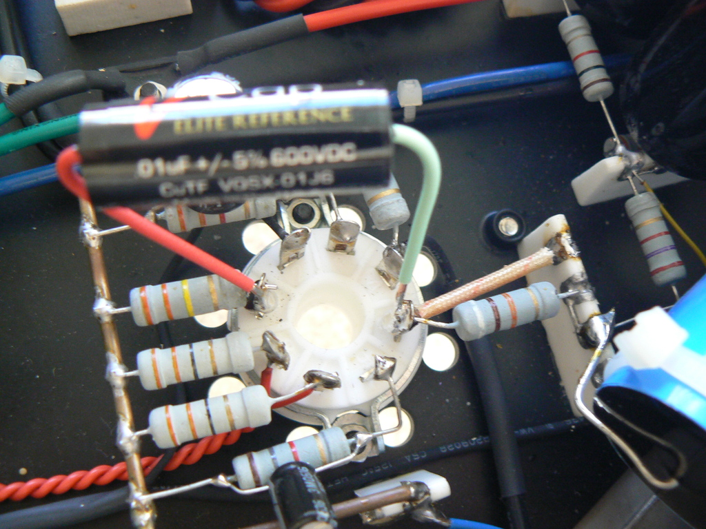
Posted below are pictures of the insides (the "guts") of my current JP-80 "phono stage". What readers will see may look "messy", but it is the result of hundreds of modifications over a 25 year period. Was it all worth it? Definitely, because I know of no other phono stage, commercial or otherwise, at any price, that is its overall equal when it comes to reproducing music naturally and completely. It's admittedly impractical to exactly duplicate all the modifications of this JP-80, but that is irrelevant to me at this time.
Explanation- This is a close-up of the two (.47/600V) CuTF capacitors that were most recently installed, in May 2014, and which are the subject of the report above. As can be seen, they barely fit between the space of tube sockets #1 and #2. Also...
1. The RCA inputs, for the phono source, are at the very top of the picture, and the furthest to the left of the three inputs that can be seen. A 47K Vishay loading resistor can also be clearly seen between the top RCA inputs.
2. The various Silver capacitors, on either side of the CuTF caps, are REL Teflons. They were originally the signal caps themselves 10 years ago. Now they are (the critical) "de-coupling" capacitors, providing filtering and quick energy to the circuit.
3. The tiny resistors and caps between the two CuTF caps, and connected to tube sockets #1 and #2, are the JP-80's RIAA equalization feedback loop. The current RIAA values are those recommended by Dr. Stanley Lipschitz.
4. The third tube socket, seen at the very bottom, was meant for the "cathode follower tube". However, it is not being currently used. Removing the cathode follower (20 years ago) provided a huge improvement in sonics, but at the price of far less direct amplifier drive capability. It is the reason why this phono stage can not directly bi-amplify without "assistance" from either a "buffer" or an active line stage.
5. Observant readers will notice some "collateral damage" on the red plastic insulation, protecting the copper grounding bar bridging the two channels. This was obviously caused by a "rogue" soldering iron.
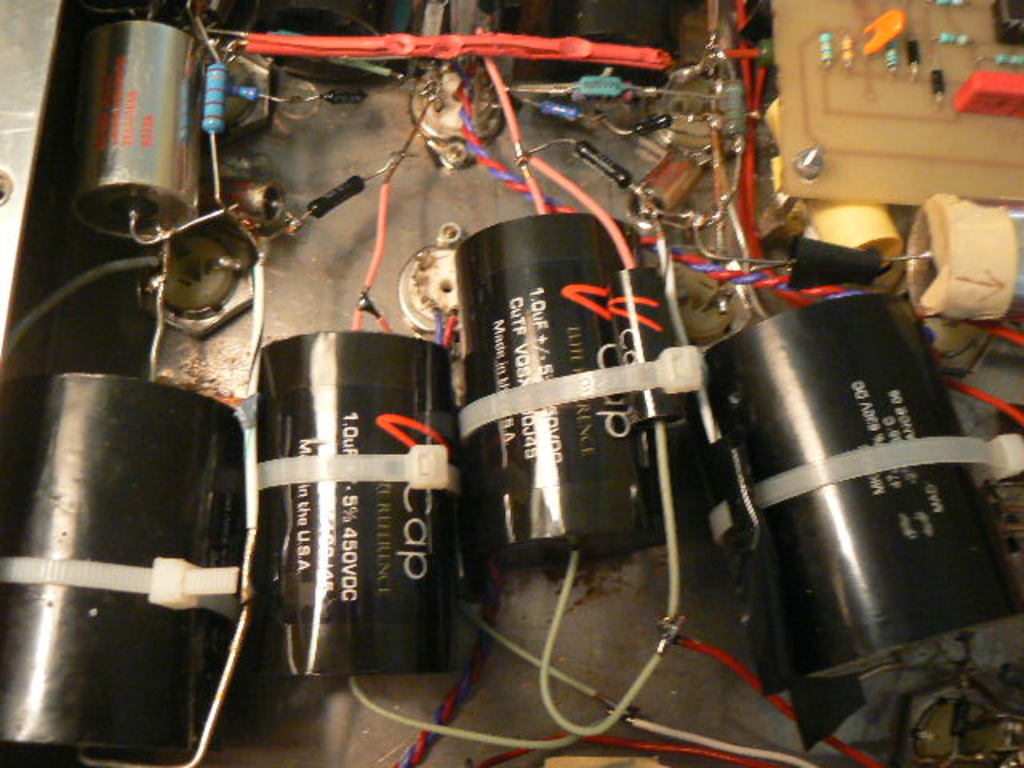
Explanation- These are the two 1uf/450V CuTF output capacitors that I reported on in 2013. Readers should also notice they have a .01 uf bypass cap as well, though one of them is obscured. Also...
1. The two huge caps, on either side of the CuTF caps, are 47 uf Solen de-coupling caps, providing local energy and filtering to the circuit. They were the largest value I could fit. They are augmented by smaller values as well, including REL Teflons (upper left).
2. All four large caps are anchored down to the chassis (notice the plastic ties). This is to prevent them from moving and vibrating in sympathy with exterior vibrations. Any vibrations can cause noticeable distortion and other sonic problems. Fortunately, the "antidote" is quite cheap and available at any hardware store.
3. The signal from these output caps goes directly to the selector switch (not seen), and then directly to the RCA outputs (not seen). The two volume pots (not seen), along with everything else, are bypassed. The load to ground on these output capacitors is 1 million ohms. (Important - I originally used 10 million ohms as the load, but this eventually caused a problem at ultra-sub-sonic frequencies, and even shut the unit down. There was no sonic downside when lowering the load from 10 to 1 million.)
4. The 47 uf Solen caps are "metallized" film. If they were "film and foil" (like the signal caps), they would be much too large to fit into the chassis.
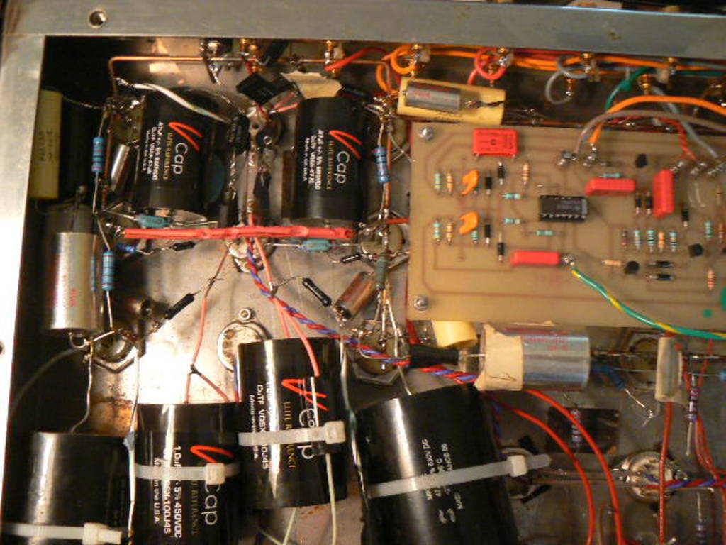
Explanation- This is the complete circuit of my modified and gutted Jadis JP-80. The existing direct signal path is this: RCA Inputs - 12AX7 - .47 uf CuTF - 12AX7 - 1 + .01 uf CuTF - Selector Switch - RCA Outputs. (The selector switch and RCA outputs can not be seen in this picture.) Also...
1. The JP-80's (mediocre) line stage, seen partially at the bottom right (tube sockets #4 and #5), has been bypassed for more than 20 years now.
2. The circuit board on the right, which contains the muting circuit, has been bypassed. (This is potentially dangerous, since powerful pulses are generated when the Jadis is turned ON or OFF, deliberately or not.)
3. The 1 uf CuTF caps are not quite twice as large as the .47 uf caps because they are built with a lower voltage specification; 450 V compared to 600 V.
4. There is not even one resistor in the direct signal path. (Only in the RIAA feedback loop, ground loading and power supply.)
I made extensive modifications on the Golden Tube 300B mono power amplifiers over a 10 year period. These modifications, in part or in whole, can also be used on most other tube power amplifiers.
Here is what I did in general terms, but without any precise details and explanations. If you don't fully understand what is written below, don't even think about doing it yourself. If all this looks like "child's play", then I would still do only one step at a time, so if you do make a mistake, you'll know exactly the cause.
1. Coupling capacitor is changed to a V-Cap Teflon, either .22 or .47uf 600 volts
2. Entire power/filter supply (B+) are Solen metallized capacitors (two 100uf/630 volt cans per channel-on top of chassis)
3. Decoupling cap, near the input tube, is also a Solen metallized, 20uf, with two extra film and foil shunts on each
4. Each 100uf B+ cap also has two extra film and foil shunts inside the chassis
5. RCA female placed near input tube, on top of chassis, with a good grounding resistor and quality wire to input tube
6. Speaker binding posts placed near output transformer (on long side of chassis)
7. All electrolyic capacitors in the entire power supply are removed and replaced-See #2
8. 6SL7 and 6Z34 are both highest quality NOS, plus KR, TJ Full Music SE or Shuguang Treasure "Black Bottle" 300B-Z
9. Quality cable installed from 300B to output transformer primary
10. Decoupling caps, film and foil, added after choke directly to the output transformer
11. Herbie's tube dampers placed on all 3 tubes
12. Walker SSS treatment applied to all pin tubes
13. Coincident power cord
14. Each amplifier will have to be rebiased because of the change of output tube and B+ total capacitance
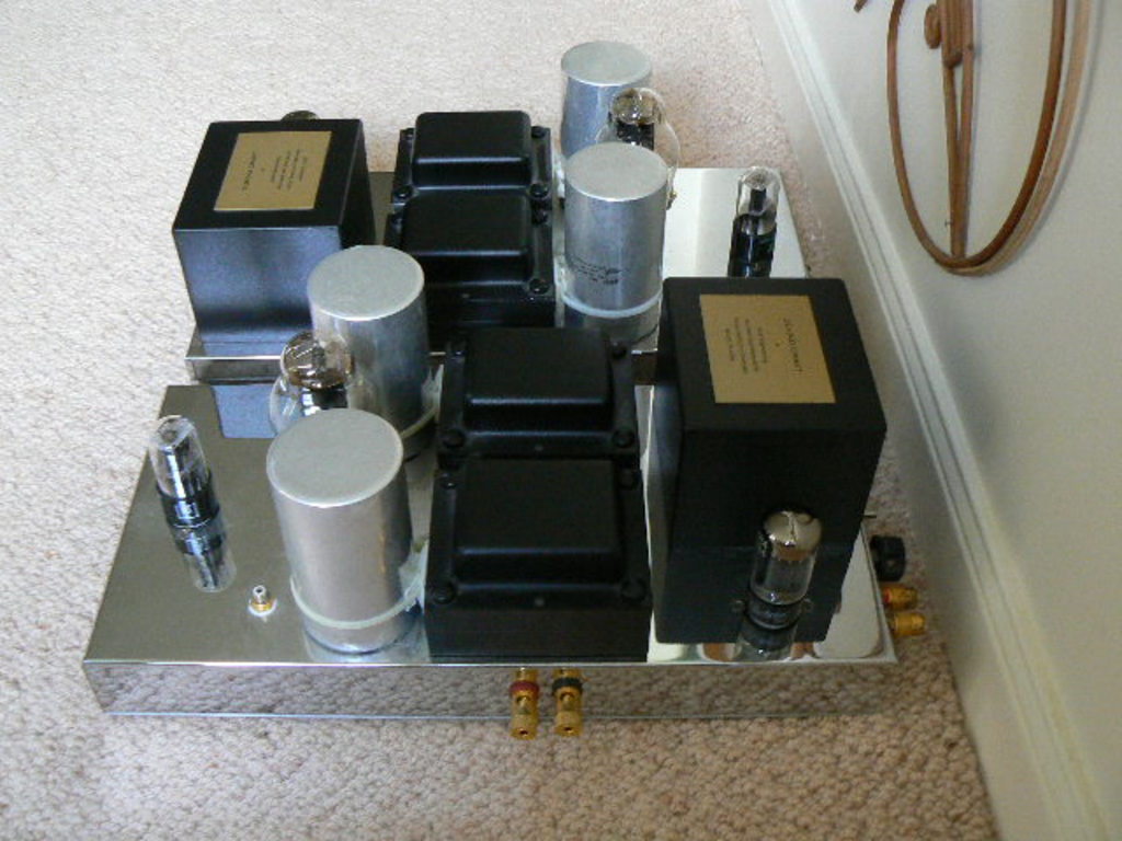
Below are now posted two pictures, outside and internally, of my personal Golden Tube 300B amplifiers, taken just before they were sold, which should assist a modifier.
Teflon Coupling Capacitor Modification and Comparisons
After having the latest version of the Frankenstein amplifier in my system for around 5 years, I decided to make a serious effort to improve on its already outstanding performance, if possible, while simultaneously satisfying my curiosity about the relative ranking of the finest coupling capacitors I've heard (all Teflon). I was initially inspired to start this project by a resourceful reader.
I'm quite excited about sharing the results of my experiments, which should prove helpful to not only the owners of the Frankenstein, but also any other high quality SET amplifier, especially those with no feedback. There were 3 direct comparisons made (plus a "bonus"), and the results may prove to be even revelatory to some serious audiophiles who are willing to think and act "outside the box".
I could have performed this comparison years ago, but I didn't know that the Frankenstein amplifier even had a coupling capacitor in the first place. This was because of a posting error within the Coincident website's description of the Frankenstein (since corrected). Further, I also didn't have the required V-Cap competitor available as well, so I guess that this delay was an unavoidable "destiny".
In any event, here are the facts: The Frankenstein uses a Solen .47 uf (film and foil) Teflon capacitor to go from the 1st triode to the 2nd triode within its 6EM7 driver tube (an Octal dual-triode tube). The competing V-Cap .47 uf Teflon cap came out of my Jadis JP-80 "phono stage" when it was itself replaced by the latest V-Cap CuTF version of the same capacitor. Both of these capacitors were obviously well broken-in, so that was not a factor in the final results, which are...
The two caps are both outstanding, but the V-Cap is slightly superior. It's a little better at vibrato, which was the biggest difference I heard. It doesn't "stick" as much, almost like the difference between a slide and a series of tiny steps to reach the same destination. Other things are quite similar. Still, the V-Cap is a touch quicker, cleaner (like better cartridge tracking), more refined, delicate and immediate, and it has a lower sound-floor. However, these improvements are all subtle and are definitely no big deal. I would say that most are Level 2 improvements, which means you will probably not even notice them after a minute or so. Also, it must be remembered that I conducted these experiments on an ultra-high resolution system, which means that what I heard may not be as noticeable on even a system that would normally be considered excellent.
So, what are the practical consequences of these results? While the V-Cap is better, I don't believe the mainly subtle improvements are worth making the switch considering the costs involved, so I don't advise it. There is also the matter of break-in, which means the V-Cap will actually sound worse than the Solen for literally hundreds of hours before it is finally optimum. What about those starting from scratch (DIY projects in particular)? In that instance, the V-Cap may be worth it considering the long-run, even with the extra costs and extended break-in, but...
There is another alternative to seriously consider: The latest CuTF V-Cap, which is the finest capacitor I've ever heard. The CuTF is definitely worth moving to, because while the costs are even higher, so is the performance gap. So, at this time, I would advise any potential modifiers to ignore the original V-Cap, if they already have the Solen Teflon in their amplifiers, and going instead directly to the V-Cap CuTF. And this is my same advice considering those "starting from scratch". In short, the extra cost for the CuTF caps is well worth it in every situation.
However, there is even another option, which is somewhat radical and ONLY appropriate and useful for those audiophiles who are Bi-amping. This option requires a detailed explanation so, just below the two pictures, there will be an "Intermission" before the next comparison.
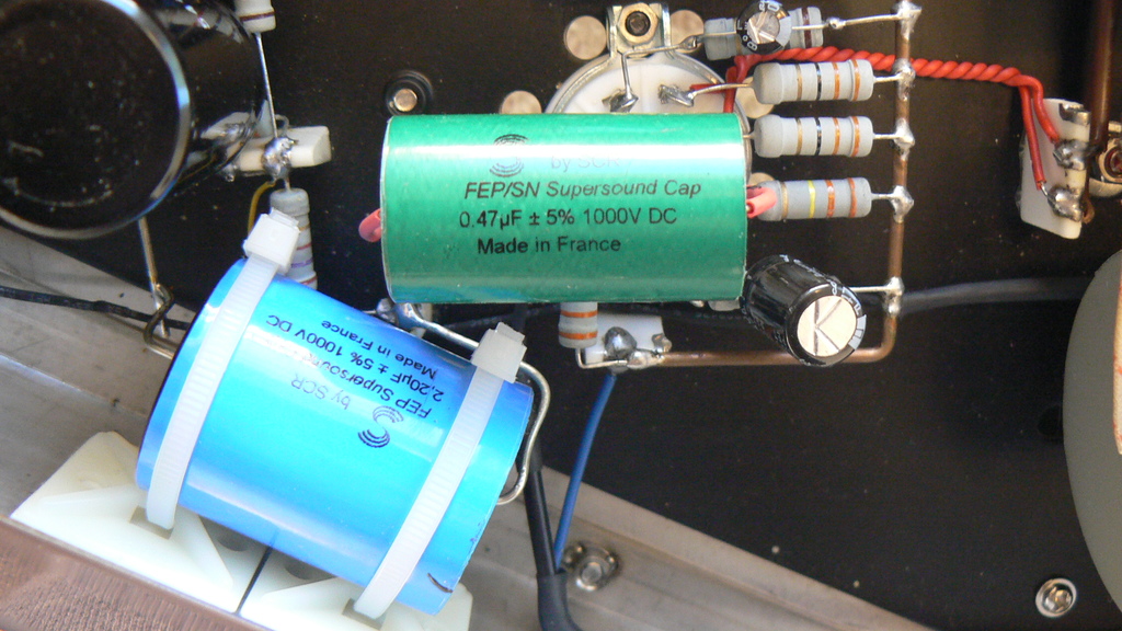
Explanation- This is a picture of the inside of one of my Frankenstein amplifiers, completely stock and without any modifications. Also...
1. The green capacitor is the .47 uf 1000V Solen Teflon Film and Foil, which is in the direct signal path. This is the stock coupling cap that has now been replaced.
2. The baby blue capacitor, just below it, is a 2.2 uf Metallized Solen Teflon cap, which is the de-coupling cap for the Frankenstein. (A film and foil Teflon, 2.2 uf cap, 1000V, if it existed, would be too large to fit inside the amplifier.)
3. Important Note- This is the first time I've ever seen, or even heard of, a quality Teflon capacitor being used in the power supply of a commercial electronic component, at any price, let alone at the cost of the Frankenstein. (Since this was posted, I have found another qualifying component, from Backert Labs, and I assume there must be others as well.)
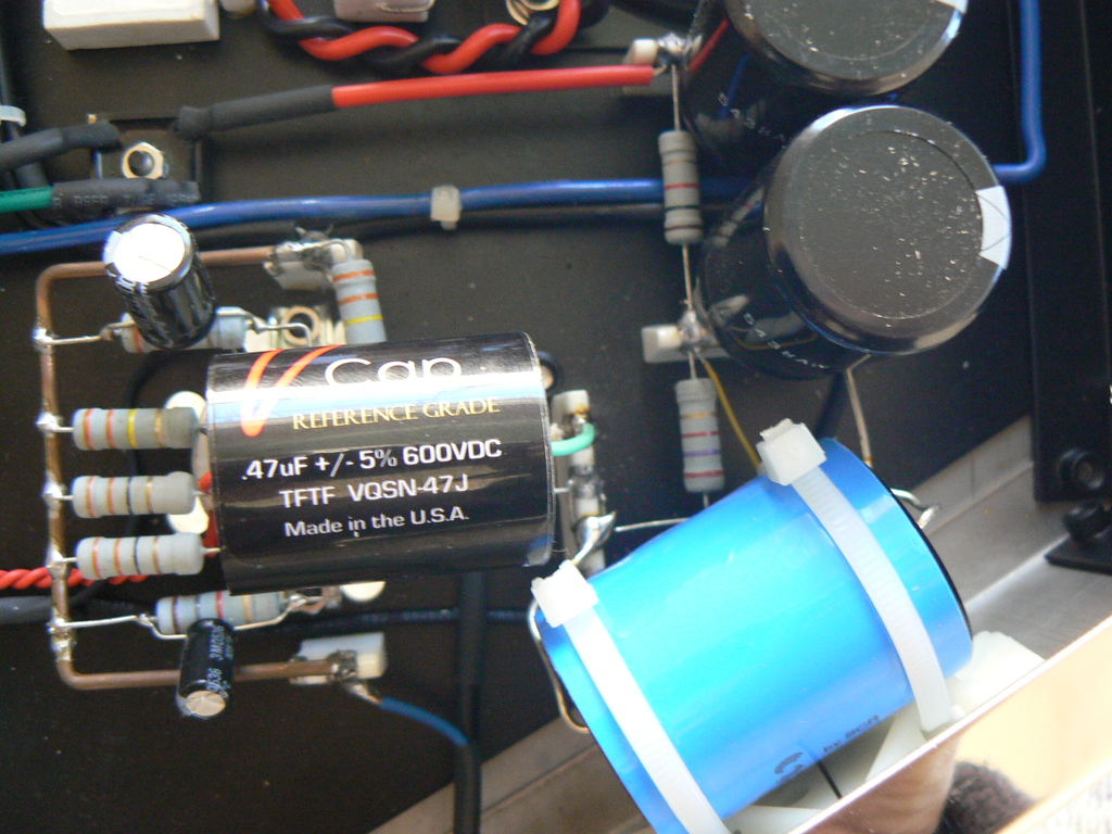
Explanation- This is the inside of the second Frankenstein amplifier, which is a mirror-image version of the above amplifier. As can be seen, nothing has changed except the replacement V-Cap capacitor, which has the same .47 uf value as the stock Solen cap, though it is rated at 600 volts, while the Solen is rated at 1,000 volts. This may be a reason why the two caps sound so similar.
Just as I was about to order two .47 uf CuTF caps (one per channel) for the Frankensteins, I had an audio "epiphany" of sorts. I was finishing up my review of the Coincident Dragon II amplifier, and was discussing the important issue of bi-amping, when I suddenly realized that I didn't need large .47 uf caps for the Frankensteins, since it was only amplifying the Pure Reference monitors, which had very little response below 80 hz. Accordingly, I thought I should first try a .01 uf instead. To make the comparison fair, I would use the exact same type, a .01 uf V-Cap Teflon at 600 volts, and I just happened to have a matched pair of them laying around, previously removed from the Jadis JP-80 (as was the V-Cap .47 uf), and they were completely broken-in.
However, I also realized that my theory, while looking fine on paper, may not work in actual practice. There was a rather obvious potential problem: The deep bass would now be rolled-off with a .01 uf cap, but would it also be noticeable, and cause an audibly lean sound? The actual math was simple and indisputable: with the Frankenstein's 330K loading resistor, the . 47 uf stock cap was down 3 db at around 1 Hz, while the .01 uf cap would be down 3 db at around 48 Hz, and it would also drop another 6 db every octave. That's quite a difference. The big question: Would being down 3 db at 48 hz (and down 9 db at 24 hz), on the monitors alone, be audible? (The subwoofers were completely unaffected.) The only way to find out was to try it out. The results...
To get quick and relevant results, for the first few hours I listened intensely only to the monitors by themselves (and thus with my system's subwoofers turned OFF). My goal was simple: If I now heard any type of leanness not noticed before, the experiment would be considered a temporary failure, and I would then go on to Plan B*. Fortunately, there was no (extra) leanness, no matter how hard I tried to expose it with every type of music I had available. The Bottom Line- The Pure Reference Monitors had just as much body as before, and this initial success allowed me to then listen for, and note, any other sonic changes I could observe.
The sonic differences were almost immediately noticeable and, even better, all of them were positive: The sound was slightly cleaner, faster, more relaxed, and less homogenized. It was also a little more more direct, immediate and transparent. The amplifiers sounded like they had a bit more power and control. This latter improvement was very similar to what you hear with better cartridge tracking. All in all, while they were not dramatic, I was obviously very happy with the results, but they were not surprising to me. Why? That answer, which is the most important point of this entire article, will be posted below, after (Bonus) Comparison No. 4.
The next comparison was inevitable. I was initially going to order the latest .47 uf CuTF capacitors, only to decide on trying the V-Cap .01 uf first, and then finding success. So it only made sense to now order a matched pair of CuTF .01 uf caps and then compare them to the original V-Cap .01 uf caps now in the Frankenstein, and that is what I did. One problem though, unlike the V-Caps, the CuTF caps were brand new, which meant an extended** break-in. This was the reason why this article wasn't able to be finished on a timely schedule.
*My "Plan B" was to go to a .02 uf CuTF cap, which would have a -3 db point of 24 Hz, instead of 48 Hz. I felt certain that this larger value would not cause any leanness. In the end of course, Plan B never needed to be implemented.
** The .01 uf CuTF cap arrived with two days of prior break-in on the manufacturer's own "special device". After the installation and gradual improvements, there was a serious performance "jump" somewhere around 220 hours of play, which is the main reason for the delay. I had to wait for it to finally settle down before I was able to come to a conclusion I was confident with.
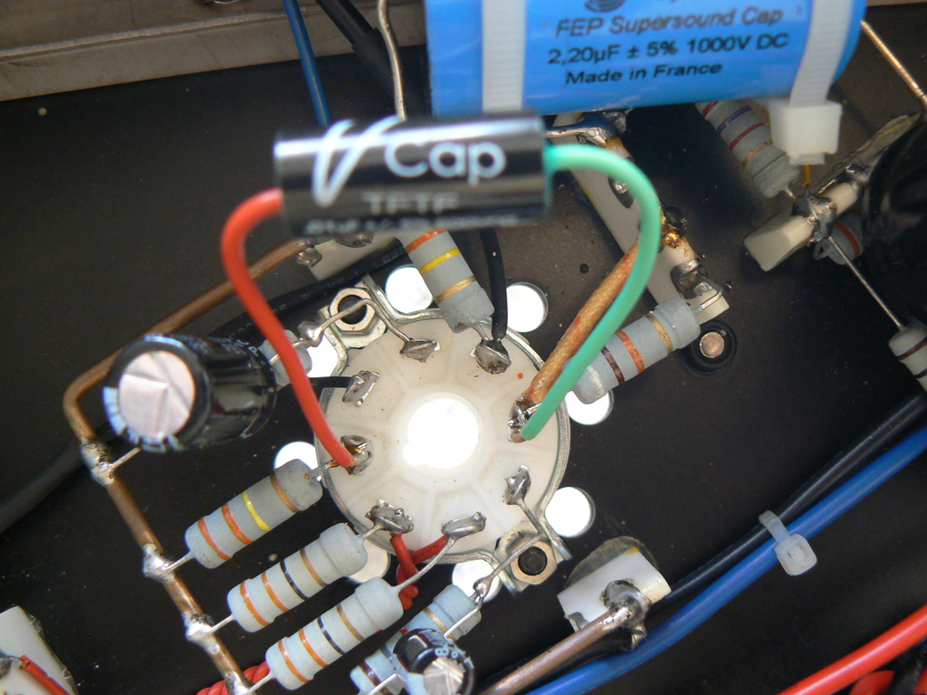
Explanation- As can be seen, the replacement .01 uf V-Cap capacitor is the exact same type as the .47 uf V-Cap seen above. There is one small difference though in its implementation; The .01 uf cap is soldered directly from one tube pin to a second tube pin, while the .47 uf was soldered from one tube pin to the far side of the short yellow wire seen in the picture, so the signal had to go through one extra solder joint plus the said wire before reaching the second tube pin.
Almost immediately, one could observe that the CuTF was superior to the original V-Cap, though it took something like 400 hours of play to hear the full extent of the improvements. The CuTF was superior in reproducing harmonic content and natural body, musical flow, purity and dynamic contrasts. It was also a little more direct and immediate, with less homogenizaiton, and had a lower sound-floor, with all the associated musical benefits which that provides. This was all deeply satisfying, and adding much to the appreciation of the music, both familiar and unfamiliar. However, it is important to also note that the sonic differences between these two .01 uf signal capacitors were not as noticeable as when I earlier replaced the V-Cap output capacitor, in the Jadis JP-80, with its CuTF equivalent back in 2013 (see The Modification File below for the specific details).
I originally hoped that since this was the final V-Cap to CuTF replacement, there was a good chance that it would also provide the largest sonic difference (which is consistent with the "weakest link" theory). As it turned out, while it was close, this was overly optimistic. However, I soon realized, in hindsight, that I had overlooked two obvious issues prior to the actual comparisons:
1. The .01 uf CuTF replacement only effected the Frankenstein (and the monitors), while the earlier JP-80 CuTF cap replacement effected the entire system full-range.
2. The tiny .01 uf V-Cap in the Frankenstein had far fewer inherent sonic "deficencies" when compared to the (200 times!) larger 2 uf V-Cap replaced earlier in the Jadis. Thus the room for any further sonic improvements would be much smaller.
There were other observations also worth reporting:
In general, the above mentioned sonic improvements were most easily noticeable only with really good recordings, especially heard late at night. In other words, there was very little difference (improvement) early in the evening and/or on (below) average recordings. In fact, the two capacitors sounded almost the same on poor recordings, no matter what the hour, and this isn't the first time I've experienced something like this. So, what does this all mean and are there any explanations that make consistent sense?
I have two theories that may explain these observations:
1. The incoming AC is now most likely the limiting factor (the weak link) in my current system. This explanation seems particularly appropriate because it would fully explain the exceptions observed during late night listening sessions.
There is also the second issue concerning the surprising lack of improvement in reproducing mediocre recordings, which requires another theory.
2. It is possible, if not probable, that these mediocre recordings are missing the type and amount of musical information which would allow a listener to hear any differences once an audio system reaches a certain (high) level of performance. This requires further explaining...
I've long argued (along with others) that the finer the audio system, the easier it is to hear the sonic differences between recordings (and also other components, cables etc). This only makes sense, since the better the system, the less "masking" of the recording, thus allowing its true individuality to be heard. While I am still convinced that this theory is true in general, my most recent experiences, while confirming it, must now also add a condition (or "qualifier") to it as well.
The condition is this: At a certain point in a system's development, it is eventually the recording itself which may become the limiting, weak-link factor. Accordingly, any further system improvements will result in negligible, or even no, audible improvements with mediocre and/or poor recordings. In other words, the better the system, meaning the closer it is to "perfection", the better (or more challenging) the recording must be to separate it from "perfection". (I plan to discuss this important issue in further depth sometime in the future.)
Explanation- This .01 uf CuTF cap is a direct replacement for the .01 uf V-Cap capacitor seen just above. They are also both soldered to the exact same tube pins.
There was one final experiment that looked very promising. I would use the .01 uf V-Cap, which had been removed (and replaced by the CuTF .01) during the last experiment and was now available. I soldered the V-Cap .01 uf in parallel with the 2.2 uf Solen Teflon (blue) capacitor seen in all the above pictures. These two caps were not in the direct signal path, but based on my earlier experiences, I still felt the .01 could "speed up" the amplifier and even allow a little more information to be captured. That was the theory.
In practice, it didn't work out as I had hoped. I heard absolutely no improvement, even subtle. Worse, I even sensed a possible compromise of the image focus. In the end, I removed the .01 cap and this time heard no downsides and maybe even a slight improvement, which verified my original assessment. So, this was the proverbial "bridge too far". However, I'm still glad I made this experiment, since it now rules out that particular avenue for future improvements. You can learn from failures as well as successes when modifying components.
The most specific news from the above results is this: The Coincident Frankenstein amplifier (all versions) can be improved by changing its coupling capacitor. Based on our findings, I only recommend using the V-Cap CuTF caps as the direct replacement. Considering the initial cost of the Frankenstein, and the sonic improvements gained with the CuTF, the cost/investment is well worth it. I also believe that the "original" V-Cap, or any other capacitor for that matter, is not worth using at this time. So, it's a CuTF capacitor or nothing. I can't be clearer than that. However, this news is not the most important point (or story) of this article. What is? The answer to that question requires a quick and concise summary of the three coupling capacitor comparisons above:
1. Solen .47 (uf) vs. V-Cap .47 - Some subtle improvements when using the V-Cap, though only after 500 hours of play. Not worth the investment in my opinion.
2. V-Cap .47 vs. V-Cap .01 - Easily noticeable improvements in many areas with the .01, plus the amplifiers even sounded more powerful and "secure". Not a "dramatic" change, but still quite important.
3. V-Cap .01 vs. CuTF .01 - Easily noticeable improvements with the CuTF in many important areas of music reproduction (after 400 hours of play). While also not dramatic, a "deeply satisfying" change.
In the end, there are only two choices:
A. CuTF .47 uf - Which will provide all of the improvements from Comparison No. 1 and (conditionally) No. 3 as well, but none from No. 2. The cost is $ 420/pair.
B. CuTF .01 uf - Which will provide all of the improvements from all three comparisons. The cost is $ 110/pair.
The ultimate choice between them totally depends on how the Frankenstein amplifiers are being utilized. If the Frankenstein is being used with a full-range speaker, which will be the case in the vast majority of systems, then the .47 uf is the only choice. However, if the Frankenstein is being used on the monitors of a bi-amped system with (sub)woofers (such as mine), then the .01 uf is the obvious choice.
There is also one exception or outlier to the above: The .01 uf (or a .02 uf if necessary) can also be used in the Frankenstein with a system based on a "mini-monitor" type speaker (like the famous Rogers LS3/5A), with its typical severe bass roll-off. This is because the .01's own bass roll-off will then be effectively masked, while all of its sonic advantages will still remain. And this finally brings us to the point or "big picture"...
The "news" that the Frankenstein amps can be improved with a CuTF coupling cap is not that important, since this was already implied two years ago, when I first reviewed the CuTF capacitors in a different context. Instead, the real news, the real point and the most critical focus of this article, for all serious audiophiles, is the important and unique sonic benefits of using the .01 uf CuTF as a coupling capacitor, if possible. Not only in the Frankenstein, but in ANY amps, usually a SET, that do not use feedback.
I first need to be clear: The CuTF .01 uf is the closest thing to a "direct-connection" that I'm aware of at this time. In fact, the .01 even has some technical and (consequently) sonic advantages over a (theoretical) direct-connection! (The claim of "sonic advantages" may appear impossible, since how can anything be better than "nothing", but please bear with me as I will make this argument below.) Accordingly, the primary goal now should be to find a method to fully utilize the CuTF .01 uf. To do so, and to understand why, means we will now have to take another quick leap back and again summarize some previous findings, this time focusing on the Coincident Dragon Mk. II amplifiers and the related and critical subject of bi-amping. The entire Dragon II Review can be boiled down to this:
The Dragon II was an improvement on the original model (no surprise). However, bi-amping was proved, once again, to be the only method to fully maximize all the capabilities of the Pure Reference Extreme. No one amplifier, at any price, could equal the combined performance of the Frankenstein and Dragon, due to inherent and unavoidable technical factors. In other words, any amplifier driving the midrange/highs will be noticeably compromised if it is also simultaneously driving the bass (woofers), and you do not have to be an experienced audiophile to observe the obvious sonic degradations. Ergo, everything else being equal, which is the only fair method of comparison, a speaker that is bi-amped will always be superior to a speaker that is not bi-amped. That, though, is only half the equation. The CuTF .01 uf is the second half of the equation...
The .01 uf CuTF can only be heard "at its best" with a non-feedback amplifier, which will usually be a single-ended-triode (SET) model (such as the Frankenstein and hundreds of others as well). Besides its inherently outstanding performance, the .01 CuTF offers these extra sonic advantages, over even a direct-connection, when it's "at its best" (as promised above);
1. The .01 will roll-off the lower bass frequencies, which means the amplifier will then waste less of its power reserves, thus providing more dynamic headroom, separation and control, plus less distortion on peaks.
2. The amplifier will also have less intermodulation distortion (which is highly irritating), because there will now be less bass energy to modulate the higher frequencies.
3. Even the speaker drivers themselves will produce less distortion, independently of the above, because they, in turn, will no longer be hopelessly attempting to reproduce the lower bass frequencies. (Needless to say, only "SET-Friendly" speakers qualify in this situation, but that is an obvious given.)
In short, what we now have is a "Win-Win-Win" scenario, which is the rarest and most welcome opportunity for a serious audiophile, whom is otherwise almost always burdened by compromised choices. It almost sounds "too good to be true", but this time it is true. So let's now summarize everything as concisely as possible:
1. When everything else is equal, a bi-amplified speaker is always superior in performance to a speaker that is not bi-amped, mainly due to the unavoidable sonic compromises in the midrange and highs when using only one amplifier, no matter what its cost and quality.
2. The .01 uf CuTF coupling capacitor, used in a non-feedback midrange/high frequency amplifier, in a bi-amped system, will provide unprecedented performance; plus greater headroom, separation and control; and less distortion from both the amplifier and the speaker drivers themselves.
The "Bottom Line", and my "Advice", is acutely obvious, singular and consistent with the above observations: Serious audiophiles should search for "SET-Friendly" speakers which can also be bi-amplified. It's that simple and straightforward.
The speakers do not have to be expensive to work, and neither do the amplifiers. This "Bi-amp/SET Strategy (BSS)" is not some sort of temporary, expedient measure to buy time until money is available to purchase something "really good". This method is for the indefinite long-term. (I've been using it myself, successfully, for almost 20 years now.) It is also important to note that this strategy does not conflict with, or attempt to break, the laws and limits of acoustics and physics*. In fact, it may even be unique in actually accepting and surrendering to these same laws, unlike almost every other system approach I've seen, from every source imaginable (magazines, websites, reviewers, manufacturers etc), since I became an audiophile almost 50 years ago.
In effect, this article is an argument for a greater "division of labor" in audio. Think: The finest audio systems have long used separate components; phono stage, line stage and (mono) power amplifiers. These separate components constitute a successful "division of labor". The "BSS" is simply taking this long proven concept to the next logical level. One speaker driver doesn't usually attempt to cover the full-frequency range, because of the unavoidable limits of acoustics and physics. I argue that there are similar limits which also apply to amplifiers. Serious audiophiles must accept these limits and then devise a plan to work with them. The BSS is just such a plan, and not simply a "theory", because it works, and works well. I know this for a fact, based on the performance of my own system and how it has positively effected such a wide variety of experienced and critical listeners.
Even better, the cost is not prohibitive. In fact, money and time are even saved by avoiding the usual audiophile chase for the technically impossible. My argument is simple: Bi-amping has inherent technical and sonic advantages because of "the division of labor" principle, and a SET amplifier's own inherent technical and sonic advantages just happen to perfectly match the requirements of this particular division of labor. How? The .01 uf CuTF effectively converts a stock SET amp into a midrange/highs dedicated SET amp, while also improving its inherent performance. To be clear, all non-feedback amplifiers offer this same option, and not just the Coincident Frankenstein, which I only used as an example. However...
Most audiophiles are not able to go to a Bi-amp/SET system in one move. There may have to be steps, so what should be the first step? Easy Answer: The purchase of a SET-Friendly speaker that can be bi-amplified, even if the current system is incapable of bi-amplification. Later on, based on the particular circumstances, numerous options will become available, and almost all of them will offer large sonic rewards for a reasonable investment. This is in stark contrast to making large investments for modest improvements, which is the typical result when an audiophile follows the recommendations and advice of commercial reviewers and magazines. Many audiophiles have an aversion to bi-amping (let alone SETs) because of the greater complexity, but the BSS can be accomplished in stages, though obviously only with first having a SET-Friendly speaker that can be bi-amped.
*Example- Why attempt to get a 5" driver to reproduce any deep bass frequencies when it will inevitably fail in this impossible quest? Worse, there's always a sonic price to pay when components attempt to go beyond their inherent capabilities, and then fail.
Within this article, I deliberately avoided using the word "dramatic" when describing the results of a single experiment/comparison, and I never did. However, when you combine all of the sonic benefits when using the CuTF .01 in a good SET amplifier (as described in the three comparisons), the word "dramatic" can finally be used with both justification and confidence. That is the reason why I felt compelled to share this "good news" with other audiophiles. Finally, it took me almost 3 decades of experiments to evolve into the Bi-amp/SET Strategy, and another 2 decades proving it to my, and my friends', satisfaction. And now these entire 5 decades of my audio life have been condensed into an article that takes less than an hour to read.
Records Used for Evaluation:
A large number of records were played during the evaluation period, but those below were used the most often:
Albeniz- Suite Espagnola- Decca/London- Space, harmonics, separation, transparency, immediacy, vibrato, sound-floor, dynamics, musical flow.
Bach- Mass in B Minor -Richter- Archive- Voice and word intelligibility, separation, musical flow, detail, space, decays. (An average sounding album, but I am extremely familiar with it.)
Vangelis- China- Polydor- Space, size, separation, vibrato, ultra-challenging dynamics. (An excellent LP to "stress" an amplifier or system, while still providing some subtleties.)
Relevant Links:
The Modification File (Passive Parts)
VH Audio (Home of V-Caps & Source of CuTF Capacitors)
Coincident Speaker Technology (Frankenstein amplifiers/Pure Reference Extreme Speakers)
TopI had planned to describe the modifications I made on the Wilson Audio WATT. The principles and techniques discussed could also be used with many other speakers. Unfortunately, the passage of time has created a problem that may not be able to be solved. I was not able to post my modification on the Wilsons at an earlier time, because other people helped me, and I don’t know exactly what components they used. Now it’s possible that the modification I performed can longer be duplicated at this time, more than 12 years later.
Details- Both of the drivers and the crossover were changed. The drivers were updated models from the same respective companies that Wilson used. I’m not sure these replacement drivers are even made any more. The crossover was based on those replacement drivers, though it was an easy 1st order, so the speaker could be driven with a low powered amplifier. That’s all I can say at this time.
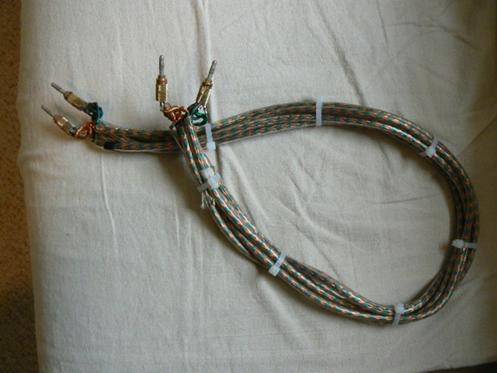
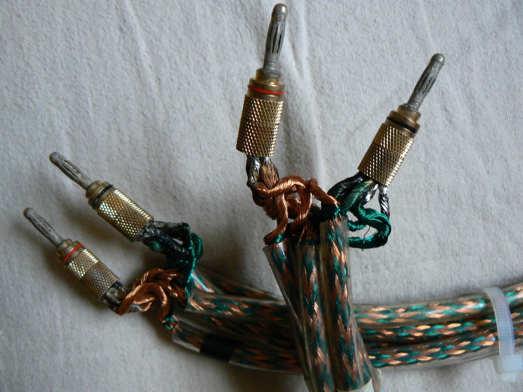
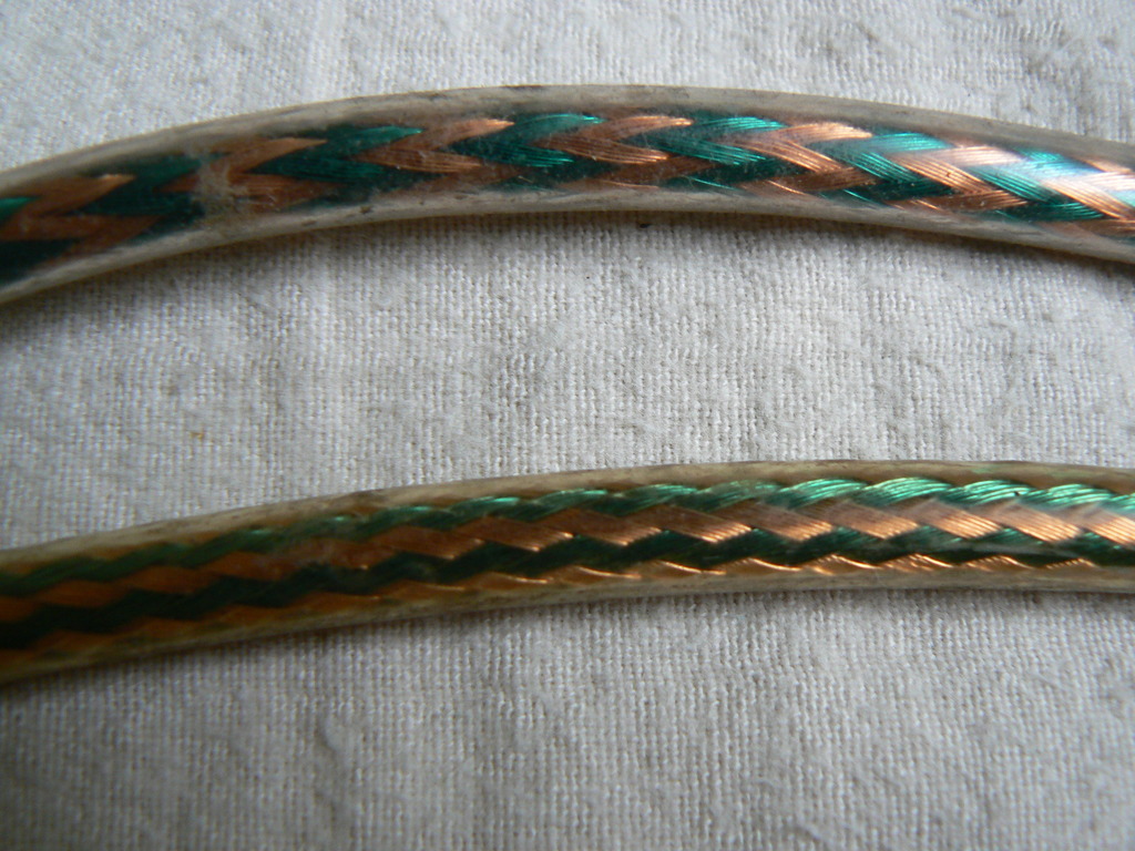
TopI will describe, in detail, the method to build Polk Speaker Cable, the only "Class A" speaker cable I have heard. The necessary material requirement is around 96 feet of single Polk speaker cable.
For now, I have digital pictures of the completed Polk cables to help anyone starting the project. Also, there are general building instructions already posted in the Reference Speaker Cable File.
I will describe and recommend the various passive parts that must be sought out and purchased by the modifier. Below is the first passive part I have written about in-depth.
According to the manufacturer, these caps require around 400 hours of break-in before they're totally optimized. I have now verified this observation. In my case, I decided to do the initial break-in within my tube tuner's output stage, so I wouldn't be prejudiced by a misleading first impression. I had around 200 hours of break-in when I initially put the caps in my amplifiers.
These are the finest capacitors I've ever heard. They are noticeably superior to the REL Teflon (HI-REL TFS103K6A), the former "champion", which, in turn, has proven superior to every other capacitor that I, and my associates, have used in the last 10 years. The list of caps we've tried includes basically every audiophile capacitor available, with the one exception of the ultra-expensive Audio Notes, which cost over $ 1,000 each. I will describe the VH Teflons shortly, but there are two relevant points to make now;
1. The preliminary comparison consisted of a VH .01uf/600volt capacitor with its REL Teflon equivalent. No larger VH Teflon capacitor has been heard yet. The cap was exchanged in my SET 300B power amp, which uses a .01uf for both coupling and as a 80 Hz filter, since the amplifier doesn't have feedback. I couldn't create a more direct, ruthless and definitive comparison, even in my imagination.
The .01uf capacitor is traditionally the most accurate and revealing within a cap "family", though it passes reduced bass because of its small value. It's similar in function to a "tweeter" in a speaker system. The larger VH Teflon caps will eventually be placed in my preamplifier in early February (2005), one stage at a time. (There are two stages in my preamp.) I won't be able to break-in these larger VH caps because of the space restrictions inside my tuner.
2. I consider the V-Cap Teflon caps to be one of the most important developments in "High-End Audio" in the last decade. I say this from the perspective of an audiophile in general, and particularly as a hard-core modifier. The unprecedented capabilities of the V-Cap Teflon capacitor has inspired and focused my thoughts concerning the inevitable issue of when audiophiles should both purchase and later sell their electronics. The "rule" I've been using myself, for the last 20 years, is finally clear and distinct to me, and I share it below.
As I promised in my initial entry on these capacitors, I have more to say about their unprecedented performance and advice concerning their purchase, plus my (now focused) perspective on modifications in general, and their important relationship with replacing and upgrading components. First, here's some relevant background information.
In the last 25+ years, I've made literally thousands of distinct modifications, meaning modifying a component and then listening to the result. They were performed on a few hundred separate components, mainly tube preamplifiers and power amplifiers, but also speakers and some tuners and CD players with tube output stages.
My very first modification was on the Dynaco Mk. VI power amps, which I had originally built from a kit. The modification was "child's play" in comparison. The Dyna modification was in two stages; changing the coupling caps and then converting the amp into triode from pentode operation. Unfortunately, it wasn't a positive first experience, because I still didn't like the amplifiers even after the modifications improved its performance, but I persisted, due to both the high performance/cost ratio, and the feeling, at least at the time, that I was building something that was better than what was available in the market. This was "egotistical", but also very pragmatic in the long run.
My most recent modification was replacing the capacitors in my current preamplifier, the Jadis JP-80, which I've now owned for more than 16 years. This relatively lengthy ownership is critical, and is also consistent with my philosophy and advice below.
Presently, I wouldn't dream of NOT attempting to modify any appropriate component that came into my possession for personal use. I look at stock components strictly as "potential" components. It's only what these components can BECOME that matters to me. I advise this same perspective to any audiophile who is a true perfectionist and who's willing to go to even extreme measures to improve their system. That brings us to the V-Cap Teflons, which are a gift from Heaven to all serious audiophiles, and particularly those who believe modifications are a requirement to reach their goal of total sonic optimization.
As I wrote above, these are the finest signal-path capacitors I've ever heard. This was an easy judgment to make, because they are superior in virtually every area of music reproduction;
1. They are the most neutral cap I've heard.
2. They are the fastest and most detailed cap I've heard.
3. They provide the most natural texture, space and low-level details.
4. They are the cleanest and purest cap I've heard.
5. They are the most immediate and transparent cap I've heard.
6. They are the most intensely* dynamic cap I've heard.
7. They provide the most separation and the least homogenization of any cap I've heard.
8. They provide the most intelligibility of any cap I've heard.
9. Their soundstage is the most focused that I've heard.
10. They have the tightest, cleanest, most natural and most impactful bass I've heard.
11. They have the most extended frequency extremes I've heard.
12. They have the lowest "sound-floor" of any cap I've heard.
*Their dynamic force is more like a bullet than a shotgun, instead of just becoming "louder", which is why I used the preface "intensely".
For a simple audio analogy, they sound like a combination of the finest solid-state and tube electronics in one super component, with no downsides; possessing both precision and natural information. From a different, more practical, perspective, these capacitors turned previously random sounds and noises into "music".
This description is all based on my comparisons to the capacitors that have previously proved to be superior to every other cap that I, and my associates, have used in the last 10 years; the Rel Cap Teflons. I don't want to give the impression that the differences between these two Teflon capacitors are "dramatic" or "night and day", because that isn't true. The V-Cap Teflons are superior in basically every area, sometimes easily noticeable, and sometimes by the tiniest margin, but any advantage is always in their favor. On the other hand, the present performance gap I'm now hearing should actually increase over time, since the V-Caps in my system are still not totally broken in. Because of this, my final assessment may change.
One must also keep in mind that the Rel Cap Teflons themselves are still noticeably superior to all the other caps we've heard, which, accordingly, places the V-Cap Teflons far ahead of any other cap we are aware of at this time. This means replacing any capacitor with the V-Cap Teflons, other than the Rel Cap Teflons, should provide "dramatic" improvements, at least after they are fully broken-in.
I have 3 amplifying stages in my system that require coupling capactiors; 2 in my preamplifier and 1 in my amplifier. They all now use the V-Cap Teflons, but the results (improvements) were not the same in each instance. This means "priorities", particularly if you are on a budget, and with the high costs of these caps, that is quite understandable.
The largest improvements I heard were in the "no-feedback" positions. This was in the power amplifier, a SET design with no feedback, and also on the output of the preamplifier. The third stage, between the first and second tubes of the preamplifier and within the RIAA feedback loop, offered the smallest improvement, even though it's the first capacitor in the signal path. So my advice is straight forward here; change the capacitors that are NOT in a feedback loop first, though all of them should be changed eventually.
The arrival of the V-Cap Teflons has focused my thinking on both modifications in general and the more important issue of when audiophiles should change their components. These two subjects are now inseperable to me, and I want to explain my thinking, because this is what I've been doing for the last 25 years without even realizing it.
Like all serious audiophiles, there's nothing more exciting for me then finding a component that dramtically improves the performance of my system. It's that "excitement" and intense pleasure that makes us "audiophiles" in the first place, and is the reason why we are constantly on the look-out for something "better", regardless of whether it is new, used, cheap, expensive and difficult to find and set-up.
However, as our system improves, our personal priorities come into focus and the choices slowly narrow over time. Then the shrinking "degree" of potential improvement becomes, along with the increasing cost, the limiting factors effecting our never ending desire to "move up". How does one deal with the inevitability of "hitting the wall"; both technologically and financially? There is no one answer for everybody, but here is my own method, evolved over decades of constant upgrading, which successfully combines an unlimited quest with a limited and unpredictable budget.
I always "Go all the way" with what I have, thus creating my personal "Reference", and then try to improve on that standard. To "go all the way" means modifying your existing (reference) component as far as you reasonably can. This is what I've done with the Jadis JP-80* phono stage.
Let me be more step-by-step specific;
Once I found the electronics that I really liked ("stock"), I continually improved them with modifications. All during this time, now 25 years* with the Jadis, I've compared it to various "competitors", with almost all of them "stock", meaning the competitors were NOT modified in ANY way, let alone "all the way", like my reference. Though this would appear to be (and is!) blatantly "unfair" to the challengers (like using steroids**), I made this decision (to cheat) for a very specific reason;
By definition, only a component that is fundamentally superior (by its basic design and/or execution) can improve on the performance of my "artificially enhanced" reference component. Once this (highly desirable) event occurs, I'm in the highest state of ecstasy as an audiophile; I will have found a new reference that will eventually, and inevitably, be FAR superior to my former reference. Why, when and how to get to that "far"? When the new reference itself* is modified "all the way".
*Personal History- The stock Jadis JP-80 had proved to be superior to my previous reference, the highly modified MFA Luminescence.
**Crude Analogy- This is like a team owner trading his "juiced" star player only after finding a replacement who was superior in ability even without the use of any "enhancements".
The conventional alternative to this "going all the way" strategy is continual "upgrading" (switching components). This is what the audio industry, including almost all of the audio magazines and 'reviewers', recommends to audiophiles, directly or indirectly. This alternative "strategy" is highly costly in money terms, and also in consuming valuable time and focus. Worst of all, most of these "upgrades" end up being small and insignificant improvements, or even "downgrades", in the long run, making them frustrating and spirit draining as well.
This can't happen with the "Modification and Upgrade Strategy". The small (fun) improvements, which are normally also small in cost, will occur naturally with the modifications. Any component change must provide a large audible improvement in the long run, since it will be the accumulation of both:
1. The original improvements heard during the comparison of the two components,
2. Plus all of the future improvements that will take place after it is modified itself.
While it was a little lengthy to explain, the "modification and upgrade strategy" is easy to understand and even implement, especially if the audiophile is capable of performing most of their own modifications. If not, this is where a friend and/or a competent and local technician will, once again, come in handy. (All serious audiophiles need friends, and most need technicians.)
The keys to making this strategy work are finding (tube) components that you really enjoy to begin with. That's the start. Then they are slowly modified until you feel their full potential has been realized. Only then, and after you are familiar with them and feel you are ready to appreciate an improvement, can the search for a new component begin; looking for one that is stock, but still appears promising. Finances and system requirements are also obvious factors that must be taken into consideration during the hunt.
They bottom line benefits of this strategy are twofold;
1. It prevents the audiophile from investing in a new (electronic) component if and when it is premature and NOT necessary.
2. Any new component passing this difficult test will have to be a significant upgrade in the long run, making "buyer's regret" a thing of the past.
Do the V-Cap Teflons have any effect on the overall strategy I've been discussing? Definitely yes, because their unprecedented performance has now "raised the bar" on the degree of improvement that can be gained with modifications. This will have an equal effect on "the degree of improvement" then required by the stock competitor to replace the modified reference component.
The resulting formula is quite simple-
Coming along for the ride is a second "rule"- When the "Stock Replacement" is finally found, its potential performance gap will also be increased by the same "degree of improvement" that the V-Cap Teflon earlier gave the Modified Reference.
1. Superior performance and longer length of ownership of their current Modified Reference.
2. A greater degree of ultimate improvement after the Modified Reference is finally replaced with the Stock Replacement and it is modified itself.
As far as I'm concerned, the only serious decision facing a modifier is whether to purchase the V-Cap Teflons or a lower quality, and less expensive, alternative, because if the V-Caps were "cheap", using anything else would obviously make no sense.
My advice is that everyone should use the V-Caps if finanically possible, even delaying the modifications until the funds are saved up. I feel this way because the V-Caps are guaranteed to optimize a component's performance along with providing an easily noticeable improvement. This optimization will give the peace of mind that you've done all that you can do, allowing you to move on and focus on something else. However, since there will be a relatively large monetary investment for common "passive parts", an unavoidable question must also be addressed.
What about the V-Caps still in the modified component after you find its eventual replacement? In this instance, I would either remove the V-Caps before I put the older component up for sale, or offer the option of the modified component with them still inside, though only if you can recover most of the V-Cap's costs, which would allow you to repurchase more of them for the replacement component. Unless money is not a factor for you, literally giving away the V-Caps for essentially nothing is not a financially wise decision.
I personally view the V-Cap Teflons as a "long-term investment", and not just more discardable parts for the first component they happen to have been installed in. From this perspective, the initial cost, as with an actual component, is no longer viewed as just another "expense". Instead, they should be seen as an integral and vital strategic part of the unique system you are putting together. As long as they're "the best", the V-Cap Teflons will also be a "necessity" for everyone who is aiming towards perfection.
Another New Reference Standard...
These are now the finest capacitors I've ever heard (for electronics*), and definitely superior to the "original" V-Cap Teflons. However, the size and degree of the CuTF's sonic improvements are no where near as large as what I experienced with the original V-Cap Teflons back in 2005 (see above, when they replaced the REL Teflon caps, which were my previous standards). These "new" CuTF capacitors have actually been available since 2010, but it has taken me almost 3 years to finally get around to them.
*I have no recent experience comparing capacitors for speaker applications.
I have a little more than 30 hours of play time on these capacitors as this is written, but I believe they are now mainly broken-in, since the sound appears to have stabilized. I heard a very subtle improvement after around 3 hours of play. At around 10 hours or so, I started hearing something much more significant, and there were further similar improvements after around 20 to 25 hours. Very importantly, I have heard no sonic downsides so far, even though I've used a wide range of recordings. As for the details...
The improvements I heard can be broken down into four major (and now familiar) sonic categories:
1. Better Flow- It sounds as though every part of every note is now "lubricated", which reduces the "mechanical" quality that is so common with reproduced music. It is actually somewhat similar to what you hear when first going to a good idler-drive (from a typical belt-drive), but without the idler's improved bass and slam etc. It's as if some of the tiny lost parts of the music have now been found, filling in to complete the picture. (This is probably related to the lower sound-floor discussed below.)
2. Superior Organization- There is better timing and more correct phasing, including the reproduction of the full harmonics of the instruments, providing them with more natural "substance" (or "body"). The cohesion of the music, top to bottom, is also improved, along with the separation, so it is also less homogenized. In combination, the music now has more "meaning". The individual musicians are just slightly larger with the CuTF (maybe because of the extra "substance"), though the "soundstage" is the same size (both width and depth).
3. Greater Immediacy- There is simply more gut presence with the CuTF, and it is also a little cleaner at the same time. (This was observed by me only after more than 20 hours of play.)
4. Lower Sound-Floor- The music was more "complete" (a top priority for me), thus allowing more of everything to be heard, including decays, textures and very soft transients, which sound more alive and real and dynamic. Again, this was specifically heard only after more break-in. I also believe this area of improvement is directly related, in varying degrees, to the "better flow" and "superior organization" discussed above.
All of these improvements, while noticeable, are subtle or minor in nature. I would still describe them as "important" though, especially as a whole, because they not only get directly into "the heart of the music", they also raise the performance level of the previous top "Reference Standard". However, I must strongly emphasize that these improvements, individually, or even as a whole, are not "dramatic", nor could they be when considering the outstanding performance of the original V-Cap Teflons.
When I first used the original V-Caps in 2005, three capacitors in my system were replaced, all of them in the signal-path; two in the phono stage (the Jadis JP-80), and one in the power amplifier (the Golden Tube 300B monos at the time). The Golden Tube amps are now long gone, replaced with the Coincident Frankenstein amps (in late 2006), which already have Teflon capacitors in the signal path. This left only the two capacitors in the Jadis to replace; the .47 uf coupling capacitor (with a .01 uf bypass) and the 2 uf output capacitor (also with a .01 uf bypass).
Since there is no CuTF 2 uf cap, I used their 1 uf capacitor instead, which is the largest value available at this time (2013). This smaller value meant there could have been a slight roll-off in the deepest bass, but I did not observe this, even in the slightest degree, no matter what type of music I've played. Maybe this is because the output cap is loaded with a 10 million ohm resistor.
The CuTF caps are larger the the original V-Caps. In fact, the 1 uf CuTF is actually larger than the 2 uf "original", and was quite difficult to fit inside the Jadis chassis. Further, the .47 uf CuTF is so large, that I decided to delay its installation until I knew for certain it could even fit. So the sonic description above deals with the output cap replacements alone. This is actually a purer direct test, because there is no feedback involved. With the .47 uf replacement, the RIAA feedback will have some effect and will mask some of the sonic differences between the two capacitors. Still, when I replace the .47 uf capacitors, assuming they will fit inside, I will add an addendum if I feel it is warranted.
While the CuTF's sonic advancements are relatively small (by any objective standards I can think of), they are not "academic", or some sort of short-term audiophile "fix". In fact, it's just the opposite: the longer I hear their sonic improvements the more I appreciate them. This is because they directly address one of the most underrated (and under reported) problems of music reproduction; its fundamentally (and unavoidable) "mechanical nature". This is in stark contrast to live music, which is non-mechanical and totally "human" (and unpredictable).
So, in this instance, you have an improvement that noticeably reduces an important problem, which is usually ignored by designers, if it's even discussed in the first place. I believe this particular sonic problem is ignored because it is extremely difficult, and expensive, to solve, even partially. To me, the CuTF is "liquidity" personified, and thus sounds effortless in a manner I haven't heard before. I am not referring here to high volume levels, where the term "effortless" is always used as an accolade. This time I mean at (ultra-)low and moderate volume levels, where I didn't believe there was any problem (or challenge) to begin with, which is the critical point I am attempting to make here.
Any audio component, or a passive part in this instance, that can expose a problem with the reproduction of music, which you didn't know even existed (while alleviating it at the same time), is important by any definition, and should not be ignored by any serious audiophile. This is especially true to those audiophiles who can actually use them in their component(s). So, my advice is simple, and consistent with what I advised when I first used the original V-Caps...
If you can afford the appropriate CuTF caps, and they can fit, then buy them. I know they are expensive, but there is no alternative to them, that I am aware of, at this time. Just as important, I wouldn't think of them as common "expenses", with no long term value. The CuTF caps should be considered as a normal audio "investment" instead, just like good quality (and expensive) signal cables, which enable components to perform at their best. Audiophiles rarely just give away their high quality cables when they sell their components, and that same practice should also be standard with the CuTF caps (unless someone will pay a reasonable price for them installed).
August 2013 Update- The CUTF caps did noticeably improve slightly with more hours. There is a touch more definition, further seperation and greater harmonic information. It's not a big deal, and my initial evaluation above still stands overall, but I must admit that now I'm even more enthusiastic about these capacitors.
October 2014 Update...
(.47 uf - Interstage Position)
I first installed the "original" V-Caps in 2005. Three capacitors in my system were replaced at the time: two in the phono stage (the Jadis JP-80), and one in each power amplifier (the Golden Tube 300B mono). The Golden Tube was later replaced with the Coincident Frankenstein, which, I only very recently discovered, has a (Solen Teflon) capacitor in the signal path. This left only the two capacitors (per channel) in the Jadis to replace with CuTF caps; the .47 uf coupling capacitor (with a .01 uf bypass*) and the 1 uf output capacitor (already reported on in 2013, see above for details).
The CuTF caps are much larger than the original V-Caps. In fact, the 1 uf CuTF is actually larger than the 2 uf "original". Further, the .47 uf CuTF is so large, that I decided to delay its installation until I knew for certain it could even fit. Luckily, a helpful (and satisfied) reader informed that he had already installed the .47 caps inside his JP-80, and even sent me pictures to prove it. So now I had to find the "courage" to schedule a "one day in hell" installation of the two .47 caps. That took 6 months, but I finally installed them in May 2014 (in a 6 hour job). The main reason for the 5 month delay of this report is the typical summer Florida weather, with its adverse (and unpredictable) effects on the AC, plus the resulting slow-down of the break-in process. As in the past, I always prefer to be late, or slow, then be unreliable.
*The .47 + .01 V-Caps were replaced with only a .47 CuTF cap, so I did not use a .01 CuTF cap as a "bypass" (as I did previously with the 1 uf CuTF output cap). Was there any sonic problem? No. So I don't advise using a .01 uf bypass with caps smaller than 1 uf.
As with the original V-Caps, the CuTF caps have a less noticeable effect when they are in a (RIAA) feedback loop. If I had to make a % comparison, a "feedback cap" has around 50% of the improvement of a non-feedback cap. That being stated, there were still noticeable improvements, though none of them were "dramatic"; Better separation (especially in the back of the soundstage) and longer natural decays, a more complete harmonic structure and better individuation of each musician (a high priority for me). Some areas sounded surprisingly the same, like dynamic intensity and image size. However, what I found most important, in the sense of the greatest personal impact, was the superior "musical flow". I believe this requires a further explanation...
First, I must repeat what I wrote in the 2013 CuTF output cap review: "One of the most underrated (and under reported) problems of music reproduction is its fundamentally (and unavoidable) 'mechanical nature'. This is in stark contrast to live music, which is non-mechanical and totally 'human' (and unpredictable)...I believe this particular sonic problem is ignored because it is extremely difficult, and expensive, to solve, even partially."
This "mechanical nature" is most easily heard (or sensed) with digital sources (especially mediocre CD players) and complex speakers and electronics (especially using transistors). It is also heard, though usually to a lesser degree, with records played on mediocre belt and direct-drive turntables. It is most minimized, in my experience, with simple-circuit/high-execution tube electronics and analog recordings played with all-out idler-drive turntables (or quality open-reel tapes). Importantly, it can also be heard with records that were recorded digitally, especially acoustical recordings of classical music.
To be specific, after the .47 caps were installed, I began to notice that most digital records were sounding more like analog records, and to me that is a "big deal". (One Example: Beethoven's Piano Concertos, with Murray Perahia, on Columbia.) Then I did my best to analyze "the what and the why" of what I was hearing. What I also found interesting is how I never really focused before on this Digital LP/"mechanical nature" connection until it had been noticeably reduced. The bottom line for me was straightforward; Digital records were definitely now more natural sounding and more enjoyable to listen to, which is all that matters in the long run.
My current advice is simple and consistent with what I advised when I installed the first CuTF caps in my system, with the added provision that signal caps, with no feedback, should always be the first priority, and any caps in a feedback loop a possible later option, after evaluating the former...
If you can afford the appropriate CuTF caps, and they can fit, then buy them. They are expensive, but there is no alternative, that I am aware of, at this time. I wouldn't think of these caps as common "expenses", with no long term value. The CuTF caps should be considered as a normal audio "investment", just like good quality (and expensive) signal cables, which enable components to perform at their best. Audiophiles routinely keep their quality cables when their components are exchanged, and that should be the same protocol with these capacitors (see below).
I now have a good number of high-quality used (and all broken-in!) Teflon capacitors, which I am not currently using; the original V-Caps (removed from the JP-80) plus some older REL Caps (see below). Further, I'm seriously considering using these various caps in a series of experiments in my Reference system. One Example- A Solen Teflon Vs. an original V-Cap, in the direct signal path, without feedback (Coincident Frankenstein). I've wanted to make such a direct comparison for years, and the opportunity has finally arrived. I may even use some of these Teflon capacitors in a power supply, which is normally considered "excessive", even by fanatics. However, I already own the caps, and they are just laying around, so why not? This could prove to be very interesting. Stay tuned.
Posted below are pictures of the insides (the "guts") of my current JP-80 "phono stage". What readers will see may look "messy", but it is the result of hundreds of modifications over a 25 year period. Was it all worth it? Definitely, because I know of no other phono stage, commercial or otherwise, at any price, that is its overall equal when it comes to reproducing music naturally and completely. It's admittedly impractical to exactly duplicate all the modifications of this JP-80, but that is irrelevant to me at this time.
Explanation- This is a close-up of the two (.47/600V) CuTF capacitors that were most recently installed, in May 2014, and which are the subject of the report above. As can be seen, they barely fit between the space of tube sockets #1 and #2. Also...
1. The RCA inputs, for the phono source, are at the very top of the picture, and the furthest to the left of the three inputs that can be seen. A 47K Vishay loading resistor can also be clearly seen between the top RCA inputs.
2. The various Silver capacitors, on either side of the CuTF caps, are REL Teflons. They were originally the signal caps themselves 10 years ago. Now they are (the critical) "de-coupling" capacitors, providing filtering and quick energy to the circuit.
3. The tiny resistors and caps between the two CuTF caps, and connected to tube sockets #1 and #2, are the JP-80's RIAA equalization feedback loop. The current RIAA values are those recommended by Dr. Stanley Lipschitz.
4. The third tube socket, seen partially at the very bottom in the middle, was meant for the "cathode follower tube". However, it is not being currently used. Removing the cathode follower (20 years ago) provided a huge improvement in sonics, but at the price of far less direct amplifier drive capability. It is the reason why this phono stage can not directly bi-amplify without "assistance" from either a "buffer" or an active line stage.
5. Observant readers will notice some "collateral damage" on the red plastic insulation, protecting the copper grounding bar bridging the two channels. This was obviously caused by a "rogue" soldering iron.
Explanation- These are the two 1uf/450V CuTF output capacitors that I reported on in 2013. Readers should also notice they have a .01 uf bypass cap as well, though one of them is obscured. Also...
1. The two huge caps, on either side of the CuTF caps, are 47 uf Solen de-coupling caps, providing local energy and filtering to the circuit. They were the largest value I could fit. They are augmented by smaller values as well, including REL Teflons (upper left).
2. All four large caps are anchored down to the chassis (notice the plastic ties). This is to prevent them from moving and vibrating in sympathy with exterior vibrations. Any vibrations can cause noticeable distortion and other sonic problems. Fortunately, the "antidote" is quite cheap and available at any hardware store. Caveat- If the ties are too tight, they can compromise the dielectric. Also, two ties may be better than a single tie in the center.
3. The signal from these output caps goes directly to the selector switch (not seen), and then directly to the RCA outputs (not seen). The two volume pots (not seen), along with everything else, are bypassed. The load to ground on these output capacitors is 10 million ohms.
4. The 47 uf Solen caps are "metallized" film. If they were "film and foil" (like the signal caps), they would be much too large to fit into the chassis.
Explanation- This is the complete circuit of my modified and gutted Jadis JP-80. The existing direct signal path is this: RCA Inputs - 12AX7 - .47 uf CuTF - 12AX7 - 1 + .01 uf CuTF - Selector Switch - RCA Outputs. (The selector switch and RCA outputs can not be seen in this picture.) Also...
1. The JP-80's (mediocre) line stage, seen partially at the bottom right (tube sockets #4 and #5), has been bypassed for more than 20 years now.
2. The circuit board on the right, which contains the muting circuit, has been bypassed. (This is potentially dangerous, since powerful pulses are generated when the Jadis is turned ON or OFF, deliberately or not.)
3. The 1 uf CuTF caps are not quite twice as large as the .47 uf caps because they are built with a lower voltage specification; 450 V compared to 600 V.
4. There is not even one resistor in the direct signal path. (Only in the RIAA feedback loop, ground loading and power supply.)
Relevant Links:
VH Audio (Home of V-Caps & Source of CuTF Capacitors)
Tempo Electric - "The Great Capacitor Shootout"*
Audio Circle - Capacitor Comparison Thread*
Humble Homemade Hi-Fi - Capacitor Comparison*
*These links will provide other options and different perspectives, and/or may even assist readers in finding some less costly capacitor alternatives.
I have now heard these newly developed capacitors, plus one of my associates has extensively experimented with them. The Bottom Line- They are "outstanding", and actually competitive in performance with the finest caps we've heard; the V-Cap Teflons. The Solens have two advantages;
1. They cost* quite a bit less, though they are still expensive because of the use of Teflon.
2. They break-in** much faster than the V-Caps.
In the past, I've only advised using Solen capacitors for tube (high-voltage) power supplies. Their metallized polypropylene*** capacitors are the best (and only) choice for those wanting to avoid the use of (dirty and noisy sounding) electrolytics, no matter what their cost and reputed "quality". As for signal-path caps, Solen has offered "decent" sound, and good value for the money, but that's it. These new Teflon caps are a complete change of direction for this company, because they are one of the finest caps available at any price; cheaper than their direct competition and noticeably superior to any capacitor we know that sells for less than them. The big question: Are they actually equal, or even better, than the V-Cap Teflons?
We don't know yet. There may be some sonic trade-offs, but they're close enough that it will take some strict and lengthy comparisons to come to a generally accepted conclusion on their relative merits. All we know, at this point, is that they're the two best we've heard, and we've heard everything possible, with the one exception of the hyper-expensive Audio Note caps. So what do I advise now...?
If you already have V-Caps installed, like I do, don't even think about changing them. If you can't afford, or justify the cost of, the V-Caps, but want something similar in performance, then I recommend the Solens as the next best choice, if they are affordable*. If you can afford the V-Caps, and you want to do something reasonably soon, I would still go with them, because they are the safe, time-proven and certain choice. If you have a longer time horizon, then I would simply wait until the Modifying and DIY communities make enough trustworthy comparisons to form some type of a consensus. I'll post any updates here as they become available to me. Accordingly, I would appreciate hearing from anyone who makes a relevant comparison between these two capacitors.
*Solen is located in Canada, so their prices are in Canadian Dollars, which are currently around par with U.S. Dollars.
**According to one of my associates, who "tracked" the break-in time of the Solens, it's around 100 hours, in contrast to the hundreds of hours for the V-Caps.
***There is also a new metallized Teflon capacitor made by Solen, with larger values, but it is only advised for cost-no-object power supplies, speaker crossovers or if a truly large value is required in the signal path.
TopSince the day this website was born, back in 1999, I've made it clear how vitally important I feel modifications are to the serious audiophile. Not only for simple optimization, but for "moving up" at the least cost in both time and money. In fact, in some rare instances, a component can be improved to a degree where it can be accurately described as an "improvement in kind". However, in most cases, there are lower improvement limits, and I want to recount the experience that conclusively demonstrated those limits to me. This particular incident occurred in early 1989, in my former retail store, and with plenty of witnesses:
Back then, I was going through a modification frenzy, with a huge inventory of capactitors and resistors on hand. I had just received some very expensive (for 1989) Teflon capacitors, and I was confident I would shock my friends and customers with what I could do with them. So I announced a special "shoot-out" for one Saturday afternoon. The participants would be two preamplifiers I sold: The Counterpoint 5.1, unmodified, and the (much less expensive) Audible Illusions Modulas 2C, with the Teflon capacitors installed and broken-in.
My goal was to prove that these particular capacitors would improve the performance of the Modulas to even beyond the otherwise superior Counterpoint, and for a fraction of the price. I made sure that both preamplifiers would be heard at their best, using a front-end that was compatible with both, and with an excellent system (details now forgotten) which would thoroughly reveal the differences between them. After all the witnesses arrived, and an appropriate warmup period, I played the Counterpoint first. When everyone was familiar with it, and satisifed that it was sounding "good", I then replaced it with the modified Audible Illusions. We listened again, with most (or all) of us expecting* to hear an improvement...
But there was NO improvement! First we were confused, especially me, so we put the Counterpoint back in the system ahead of schedule. Well, there was no doubt about it, the Counterpoint was still better. For confirmation, we repeated the entire process, and once again heard the same results, though during the second comparison the Counterpoint's superiority was much easier to discern. At the time, I was really depressed about this entire incidient, much more than even those customers with equally high expectations. But I eventually realized that I had now learned, first hand, the limits of using superior passive parts. It also conclusively demonstrated the critical importance of the actual circuit, build quality and the power supply to the ultimate performance of the component.
If I had to make a "General Rule" about the importance of passive parts for a specific component, using my current perspective, I would state that the better everything else is within that component, the more of a difference the passive parts will eventually make. This only makes sense, since the other factors can only hold back the potential performance enhancements of the passive parts themselves. So, the old "weakest link in the chain" analogy, used so frequently by audiophiles when discussing and analyzing entire audio systems, also works just as well when directed at the individual components themselves. For example,...
The Input stage = The "Signal source",
The Power supply = The "Amplification",
The Output tube(s) (and Output transformer) = The "Speakers",
The Internal wiring and connections = The "Interconnects and speaker cables".
In Conclusion- I believe that the concept, and practice, of viewing each individual component as a "System", in its own right, is an important step in the evolution and development of a serious audiophile.
(*This was one of the countless experiences I/we have had of "reality" overcoming "expectations", and we're obviously not unique. However, there are a number of audio skeptics who seriously claim that most components sound exactly the same, and that the only "differences" that audiophiles ever "hear" are what they "expect to hear". That means, in effect, that audiophiles can never be "surprised" when making component comparisons. That's totally absurd of course, and so is their arrogant "theory" of "only hearing your expectations" in real life.)
TopV-CAP TEFLON CAPACITORS- These are still the finest signal path capacitors that I, and all of my associates, have ever heard. However, they are not suitable for all applications; in particular, some high voltage amplifiers. Here is a letter from a reader who has such an unsuitable amplifier, with some minor editing (my bold):
"I talked to Kara Chaffee at deHavilland about the V-cap upgrade. She warned me that the voltage is too low for those caps to be used on the deHavilland. She recommends caps at least rated at 1000 volts. The V caps are only rated at 600 volts. She said she talked to the fellow who designed them, and he is supposed to design a V cap rated at 1000 volts. She also told me someone tried the V cap upgrade in one of her amps and the amp blew up."
Personal Notes- The moral/lesson here is clear. If you think your amplifier may use unusually high voltages, then check this out thoroughly before replacing the capacitors. The replacement caps should always be at least the same voltage, or higher, than the stock caps. A simple e-mail or phone call to V-Cap, or the original manufacturer, can straighten this out in no time.
This new 1000 volt V-Cap Teflon is really good news, and not only for those audiophiles who require the high voltage caps (like me). This is because it's possible that the 1000 volt cap will sound a little better than its 600 volt equivalent in many situations where the high voltage is not a requirement. The only unavoidable downside is that, everything else being equal, the 1000 volt capacitor will cost more to manufacture, and thus also cost more to the end user.
I would also like to add a short comment about deHavilland amplifiers. I haven't been able to "Recommend" a particular model because of financial conflicts. However, based on A/B/C comparisons, a couple of my associates felt that two of their models were as good, and probably superior, to an equivalent Audio Note amplifier, which sells for 10 times the price of the deHavilland models.
Here's part of a letter from a veteran reader, and past contributor, who has modified his Audio Research SP-11, a high-gain preamplifier that we've advised for years (with some minor editing and my bold):
"I'm the guy that was modifying my SP-11 by replacing all 28 of the stock .01 uf bi-pass "Wonder Cap" capacitors with V-Caps Teflons. (I also bypassed the power supply caps with .10 uf V-Caps.) Here is the verdict:
Wow! This was well worth the $ 1,100.00 investment. The V-Cap mod transformed the venerable SP-11 into, possibly, a world class preamp. Inner detail is much improved, to a similar degree that I experienced when going from the ZYX Airy-2 to the UNIverse. The mod was so successful, that a friend of mine insisted that I perform the same mod on his SP-11 Mk-II. The Mk-II has even more caps to replace. Chris, at ARC, recommended against any such modification, saying that it would no longer be a true SP-11, and the resale value would be less. This, of course, may be true, but that's ok, I have no intention of selling this puppy any time soon, and in my opinion, it sounds worlds better than stock."
The same reader later sent me instructions on how to speed-up the otherwise lengthy burn-in of the V-Caps:
"I pre-burned the Vcaps by wiring them into the x-overs of an old pair of speakers. I wired the speakers out of phase and put them face to face on the work bench. This canceled out most of the sound, then I connected them to a receiver and played music at a high level 24/7 for 700 hours. This shortened the break in time to around 25 hours. The Vcaps still needed the additional 25 hours snuggled into the circuit where they would spend the rest of their lives, in order to sound their best. It would have taken quite a while to put 400 + hours on them during normal listening."
Personal Notes- I'm not surprised with this reader's enviable results. There's a lot of capacitors in the signal part here, so there should be a major improvement. I also agree with this reader's "resale" perspective; Forget all that "resale" stuff when you're making a serious upgrade like this, which didn't even cost that much considering the final results. This is what I feel about "resale"...
Your one and ultimate goal is using and enjoying the component, not re-selling it. Example- I've owned, used and enjoyed my Jadis JP-80 for 18 years now. (In this reader's case, the old caps can always be reinstalled anyway for a "resale".) (12/06)
Here's a letter from a long-time reader with some information about a teflon capacitor that I never heard of before. His recent experiences with the best teflon capacitors, further confirm our many positive experiences with them, for more than 10 years now, and on a wide variety of equipment. There's only some minor editing, and my bold as usual:
"Over the course of the past couple years I have been doing modifications to my Aksa preamp, to try to improve performance, as well as once addicted to diy audio, modifying is part of the hobby. Anyway, I recently installed a pair of teflon capacitors, Sonic Cap Platinum’s, in two positions in the preamp; the input cap to gain stage, and the input cap to the tube grid. Both caps were full value caps, 1uf and .01uf respectively. I did the small cap first, followed a couple months later by the larger cap.
The first cap change produced a noticeable improvement, but not quite in the jaw dropping arena. However, the larger cap installation has been a jaw dropper! Everything is much as you have written in your articles on the V-cap TFTF.
The other day the Aksa preamp designer visited for a listen, was quite impressed, and is now redesigning parts of his preamp to be able to include affordable teflon caps in the unit.
I’ve read your article on the V-caps many times, as well as most everything else I could find. But V-caps are expensive! I came upon the Sonic Cap Platinum’s thru an audio acquaintance who know the Sonic Cap designer, Jeff Glowacky. Jeff runs a small diy supply house in Arkansas, and keeps such a low profile, that he is not well known at all. Bill Baker, of Response Audio, replied to an email question about comparing the V-cap to the Platinum, by writing that the Platinum was pure and precise, while the V-cap had body and texture. Bill uses both caps in his modification business.
And just today I discovered the Solen teflon caps, while browsing your site. They are a little less expensive than the Platinums. Perhaps this is due to Solen being a big manufacturer rather than a smallish business, I don’t know. Anyway, I just want to add my voice to the teflon cap converts! Just by adding that one 1uf cap to my preamp has literally transformed my whole audio listening experience. While the caps themselves seem expensive, the use of just a single pair has been the least expensive product/system upgrade imaginable!!!
I might add that for signal path applications one should use full value caps. My initial experience with teflon caps was in using a small value cap as a bypass cap on the output capacitor cap of my amplifier. This had no effect whatsoever, other than to break-in the cap. This was the same cap that I installed as input cap to the tube grid, and opened my eyes to the benefits of teflon caps. I’ve read many posts where users bypass caps with small value teflons and claim a benefit. My own experience does not bear that out and I remain sceptical. I know the high price of teflons makes one try the cheapest way possible, and bypassing is a cheap way to enter the game. But I think one has the pay the price in order to reap the benefits. And as stated above, when considered as a full product upgrade rather than a part cost, the price is really very small. Of course it also helps if you can do the work yourself.
These caps simply transform the music into something resembling actual music! And I write that as I just attended the symphony on Friday evening, and followed with 3 days of a lot of listening!
An additional note here is that Hugh Dean, Aspen Amplifers aka Aksa, is trying to enter the retail audio arena. It’s difficult to do this with a one-man business in Australia, with the primary market being the US. He is to exhibit at the 2007 RMAF in October. If all goes well, he will have his redesigned preamp complete with teflon caps and state of the art performance, all at a very affordable audio price. I say that last sentence because as I’ve browsed thru various audio things, I don’t find many audio units with teflon caps as standard. And the ones that do so are priced well above 10,000USD. One can always order the teflons as options on lesser-priced units, for additional price of course. Hopefully all the above will happen, and one or some of your audio associates/readers will hear the Aksa products.
I’ve attended all three RMAF’s, as when I am in the States I live within a half-day’s drive of Denver, and the show is easy to attend. It’s the only audio show I have ever attended and I find it to be a very good show. It seems to get better every year. It’s almost all only audio. And even if you get looked at a little funny for asking for classical music, it’s acceptable. There is enough variety of products and such that there is something there for anyone with an interest in audio.
You can read more about the Platinum caps at Jeff’s website: www.soniccraft.com* and link to capacitors, then Sonic Cap, then Platinum. It won’t say much however. In reading around, I’ve learned that the caps themselves are rolled at RTI Electronics in Los Angeles. They make many of the audiophile caps on the market."
A veteran reader has sent information about a new Teflon capacitor. Very little editing and my bold:
"There is a new teflon cap now out on the market, from Dan Wright at Modwright. You can look things up on his website, www.modwright.com. There are only 3 values of teflon caps at the moment. Pricing seems similar to the SonicCap Platinums. I believe he developed these caps in order to use them in his new preamp, which recently came out on the market. This new unit appears like it might be a very worthy unit of audition for you or your audio associates."
URL for Teflon Capacitors: http://www.audiocircle.com/circles/index.php?topic=41592.0
A reader informed me about these caps, which have been available since last Fall. I don't know yet how they compare to the two Teflon caps I've highly advised using in the recent past; V-Cap and Solen. I also don't know the respective values, voltages and prices, but all Teflon caps must be relatively pricey, due to the material costs. A link to the Audience website is in the Links File. (1/08)
A veteran reader recently informed me about an extensive capacitor shoot-out at Tempo Electric's website. I found it to be thorough, well executed and generally excellent. It is also very similar in results to my/our own experiences. Considering my strong belief on how important capacitor modifications can be when optimizing components, I feel this survey should be read (if not printed) by all audiophiles who feel the same as me. With a huge "Thanks" to Tempo, and their "gang", here's the URL:
The same reader who sent me his grid choke modification in April, which I posted above, has sent me his latest findings on this subject. Once again, I would like some confirmation, if possible, of his results from a different reader. Also, I only recommend that real experts try out this modification, since it's new and the instructions are from a non-English writer. Here they are, with some minor editing and my bold.
"Concerning my suggestion to use grid chokes as an easy replacement and cheap upgrade for tubed circuitry. Well, I found another supplier who provides a real 47k ohm grid choke at 2000Henry. The one I recommend previously, although intended for same use, is only rated at 670Henry (and checked 17.5k ohm). This betters the resistor, no matter how audiophile it is, but this newer one is dynamite! A strong bass and musicality is added to the sound. Not only that, but this 2000Henry/47k ohm is actually cheaper at $16.00 each!!!!!!!!
There is only one downside. The store is located in Taiwan, and the salesmen have poor and limited English. But believe me, follow their instructions through their Ebay store and you will receive iron gifts as some plate chokes, and cheap delivery costs too. I had one of his anode chokes (130Henry/8K2) replace a 10k ohm resistor on top of the first ECC83 tube on my phono preamp... wow! (Do a search on Ebay for "grid chokes" to find the supplier.) But you must arrange the purchase there first with an EMAIL (sigmadelta2001@yahoo.com). This way they put the price increase difference on the invoice field "mailing costs". Have some patience and you will be rewarded. They are in the process of expanding their product range and the long awaited catalog will soon be available." (8/09)
This letter, from a veteran reader, provides further observations about the positive use of grid chokes etc. There's very minor editing and my bold:
"I use grid chokes all over the place; in fact I always replace a resistor with a choke if I can (like in my RIAA correction). Both Stevens & Billington and Magnequest manufacture excellent grid chokes. Even the superb Audio Note 2 watt tantalum resistors are outclassed! Everybody ought to read the excellent articles by the (very unfortunately late Harvey Gizmo Rosenberg) about magnetics. He very correctly described how, by replacing resistors by chokes both in grid and anode, you get a much richer and organic sound. That´s my experience too; I use 40 chokes in my RIAA psu, evenly distributed on both the negative and positive B+, and also on the filaments. Try it yourself and be amazed!"
Personal Note- I added a Link to the Harvey Rosenberg's website, which is still up and running. It has a considerable amount of thoughtful and provocative information, theories and observations about audio. Rosenberg was one of audio's most avant-garde thinkers, even though he mainly used and recommended solutions from the (wrongfully neglected) distant past. He is irreplaceable and very much missed.
A reader has another view of this preamplifier, which has received virtually no "press", outside of this website, since it has come out. There's minor editing and my bold:
"I have had this component for 8 months. I would reemphasize the need to change the stock tubes. I replaced them with NOS Mullards. The Doge 8 is superb as a linestage in my smaller all tube system, where it currently resides. In this system, I essentially agree with everything stated on the site. It has both finesse and power and takes charge of the amp. At the price it is a screaming bargain.
In the main (SS) system, the Doge linestage is also excellent, with superb tonal reproduction of different instrumental colors, but I suspect that its sonic compatibility with different SS amps is more variable than with tube amps. Its dynamic punch and extended treble range is not objectionably exaggerated by my SS amps, but I think with some others it might sound overly aggressive. The high gain structure is also an issue with many SS amps. I measured only a small decibel change between Outputs 1 and 2 (~3db), although some websites insist that Output 2 has 10db less gain than Output 1. Some preamps, such as the tube Jolida Envoy, have high and low gain outputs, which are a big help in system matching. Overall, for the SS system, I still prefer my Hovland preamp, now recently orphaned, but I’ll also use the Doge.
The Doge 8 phonostage impressed me even less than your associates found, despite my only needing to use the MM tube circuit. I thought even the MM circuit noisy and a bit aggressive compared with somewhat more expensive phonostages such as the Herron I normally use. It does have significant strengths including image solidity and good harmonic structure, so I hope that its weaknesses can be corrected even if the price goes up a bit." (9/09)
A reader was very impressed with this book, and while I haven't read it myself, I also agree with the author's overall approach; optimizing what you have and avoiding component changes unless you have no choice. This is what he wrote me:
"The more I read, the more I think this book is a little treasure. It speaks a lot about Room Acoustics, 'playing the room' by proper speakers placement for a given space, how to find the best spot for the seating spot and so on and so forth. In addition, it speaks loudly against 'Upgraditis' and the need to ensure everything else in the reproduction chain is addressed before jumping into expensive and unnecessary components upgrade. I cannot agree more." (9/09)
Here is a link to the author's website: Get Better Sound
TopExternal Links (For Modifiers)
TopIf you have a question, or want audio advice and/or consultation:
Important Notice- As of October 1, 2012, there is a minimum fee of $ 10 for me to answer a simple enquiry, which means any question that I can answer quickly without research. Anything else will cost more and I will accordingly provide quotes for approval. PayPal is being used for its convenience, universality and security. If interested, click on "Ask Arthur".
There are two exemptions to the payment fees. 1. Those readers who have provided an important service (usually information that was posted) to this website over the years. 2. Those situations where I feel that I overlooked something important and/or was obscure in my post, and thus some necessary clarification is required on my part. That will always be gratis. I don't believe in being unfair or petty, especially to my own readers.
Telephone Conversations- If a reader feels it is necessary to actually talk to me directly, this can be arranged if I also feel it is appropriate. There will be a minimum fee of $ 50. Ask for the details before paying the fee.
Finally, a veteran reader wrote that I "should also have a link for (generic) donations to keep the website going". I replied that the Donation button can also be used by appreciative readers for that purpose. Needless to say, any unsolicited donation from a generous reader receives my sincerest thanks and gratitude.
To contact me for any other reason:
COPYRIGHT 2003-2023 ARTHUR SALVATORE